Page 1 2
nd
Edition – Rev 0
32-30
NOSE LANDING GEAR – DESCRIPTION AND OPERATION
33-30 NOSE LANDING GEAR
DESCRIPTION AND OPERATION
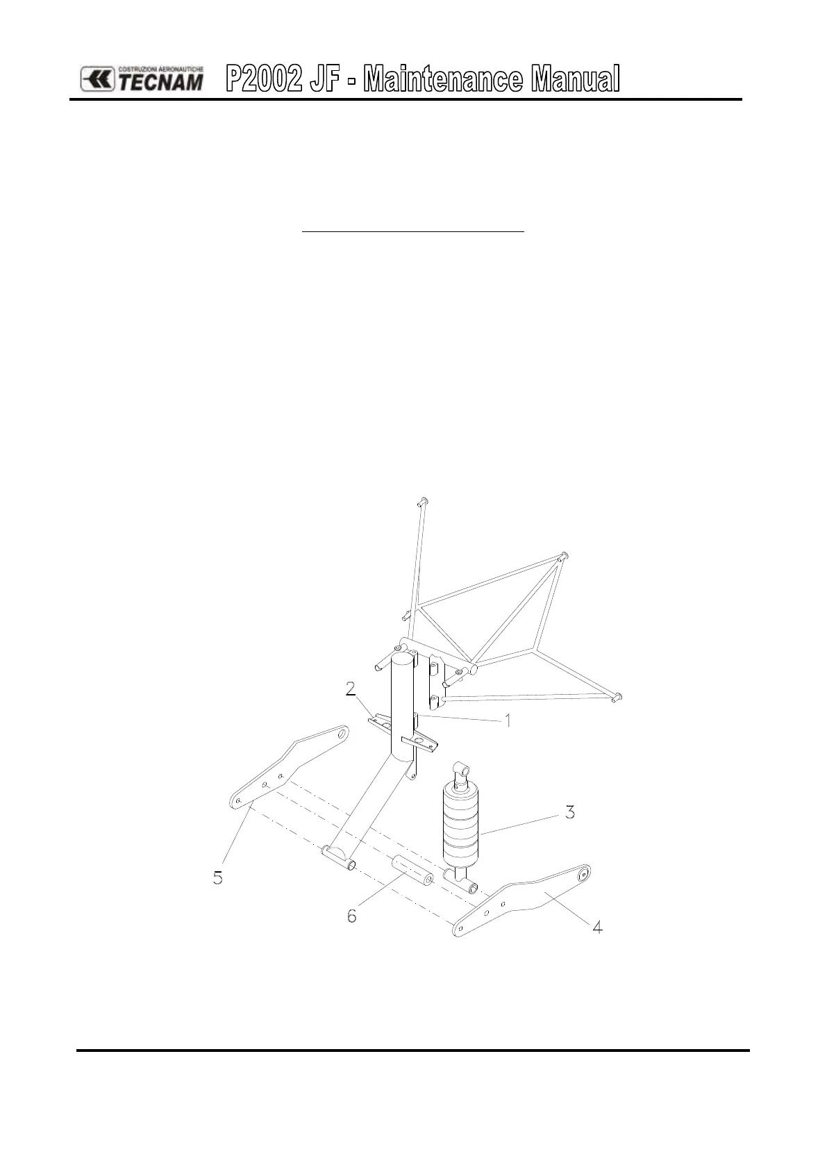
The nose gear (fig. 20) is attached to the engine mount with two hinges (1) and is equipped with a
4.00-6 type tire.
Steering motion is transmitted from the pedals through two steering tubes that are attached to the
nose gear strut by means of two brackets (2) welded to the strut.
Gear fork is made up of light alloy plates (4) & (5) and a spacer (6); it hinges on the strut leg and is
braced by a rubber-disc shock absorber (3).
Figure 20. – Nose landing gear