Page 2 2
nd
Edition - Rev 0
75-10
LIQUID COOLING SYSTEM – DESCRIPTION AND OPERATION
75-10 LIQUID COOLING SYSTEM
DESCRIPTION AND OPERATION
Standard Configuration
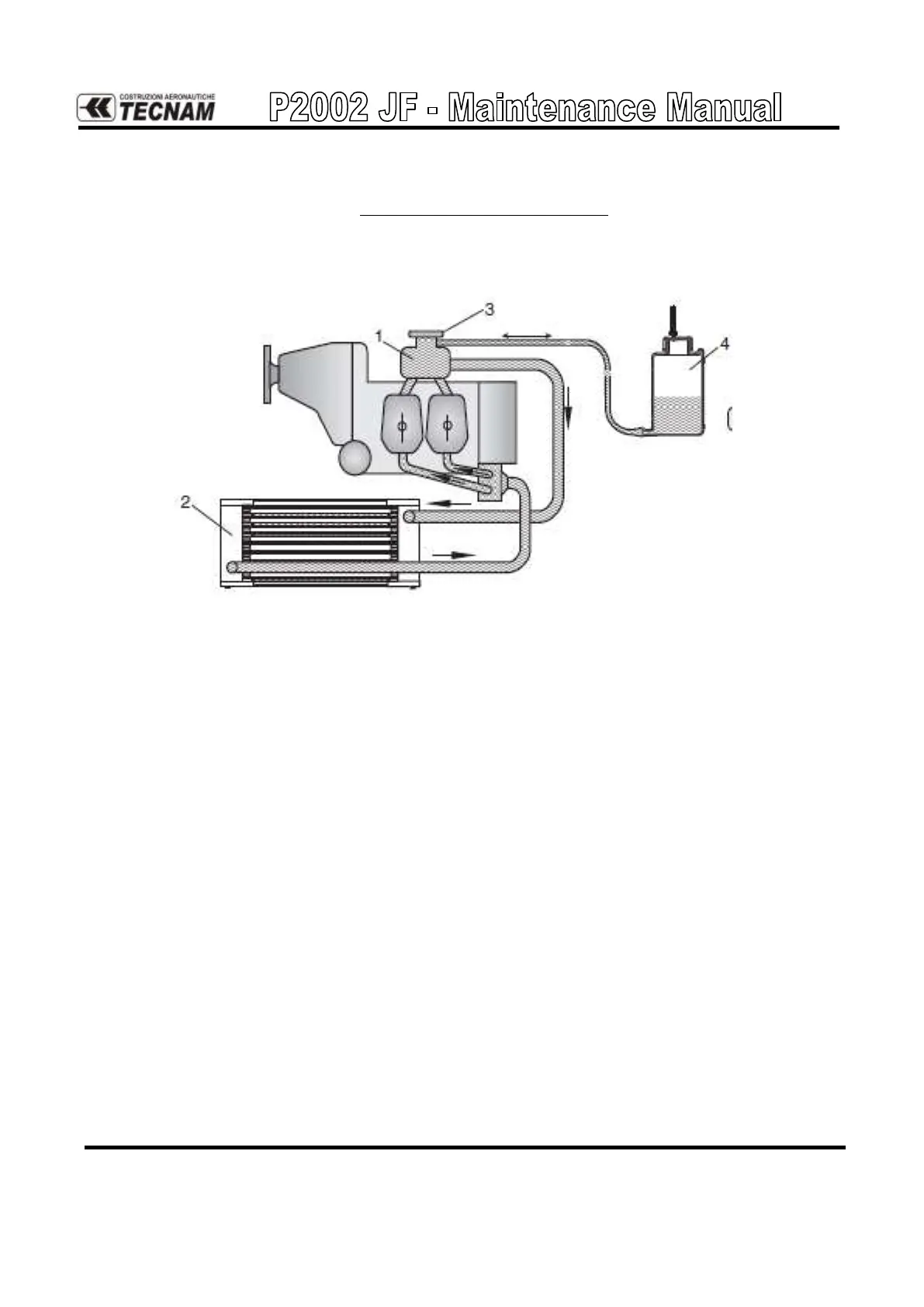
Figure 1. - Scheme of liquid cooling system
With reference to Figure 11., the liquid cooling system is a closed circuit with an over-
flow bottle (4) and an expansion tank (1). The coolant flow is forced by a water pump,
driven by the camshaft, from the radiator to the cylinder heads and then the coolant
passes on the expansion tank; the latter is closed by a pressure cap (3) fitted with pres-
sure relief valve and return valve. At temperature rise and expansion of the coolant, the
pressure relief valve opens and the coolant flows via a hose at atmospheric pressure to
the transparent overflow bottle (4). When cooling down, the coolant is sucked back into
the cooling circuit.
The system is fitted with an overflow bottle where surplus coolant is collected and re-
turned back into the circuit at the cooling down period.
The radiator is placed on the front end of the engine cowling, attached to the engine
mount.
A CHT sensor along with the related instrument located on the instrument panel (right
side).
NOTE: on ROTAX engine CHT is representative of liquid cooling system status.