Page 2 2
nd
Edition – Rev 0
55-10
STABILATOR – DESCRIPTION AND OPERATION
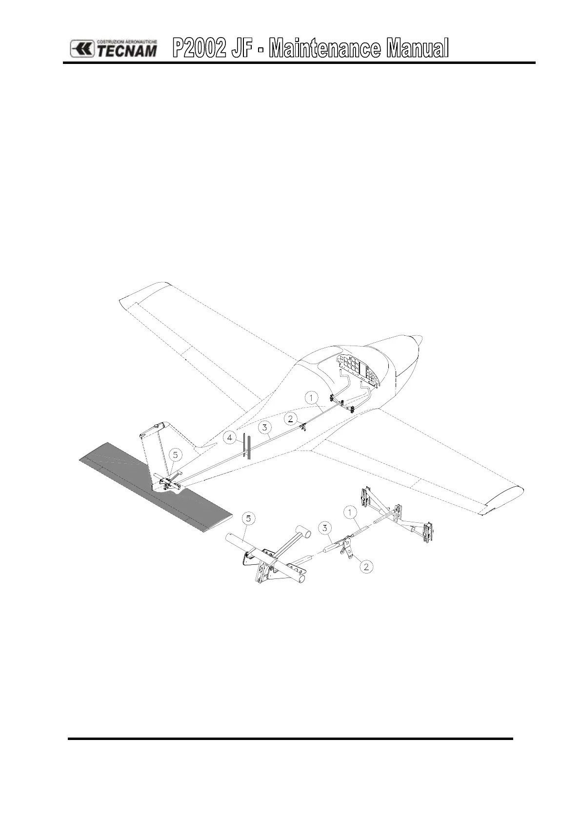
The stabilator control system is push-pull type and is controlled from the cabin via the
control sticks. Control is transmitted through a push-pull rod (1) linked to a bellcrank
(2) and a shaft (3) that runs through the tail cone supported at midsection by a bracket
(4) and connected with the stabilator’s torque tube through the aft bellcrank assembly
(5).All significant transmission elements such as bellcranks, pushrods, supports and
hinges can be easily accessed and inspected.
The aft bellcrank assembly consists of a steel tube (1) with welded horn assembly (2),
attachment for stabilator control shaft (3) and balanced weight bellcrank (4).
Counterweight is located at the end of a prong bolted to the torque tube and entering tail
cone through the tail-frame cut out.
Figure 2. - Stabilator control
Longitudinal trim control is controlled two switches on the top of each stick handle. It is
possible to select either the left or the right controls for operation. A trim position
indicator is located on the instrument panel. Trim control activates the linear actuator