Page 1 2
nd
Edition – Rev 0
27-30
FLAPS – DESCRIPTION AND OPERATION
27- 30 FLAPS
DESCRIPTION AND OPERATION
The flap system is made up of an electric actuator , a shunt, and by a position
indicator instrument. The actuator is installed in the tail cone in correspondence
with the baggage bulkhead and controls a system of pushrods that initiates flap
extension. Micro-switches positioned within the actuator automatically interrupt
current flow when flaps reach “all-out” or “all-in” positions.
A bowden-type cable issuing from the flap actuator controls flap position indicator located
on the right side of the instrument panel.
Flap extension shunt is supplied by the primary bus bar through a breaker and is located on
the instrument panel.
Shunt must be activated until desired position is reached and read on instrument :0°, TO
(15°) or FULL (40°).
During flap retraction, shunt supplies the actuator until flaps are completely retracted.
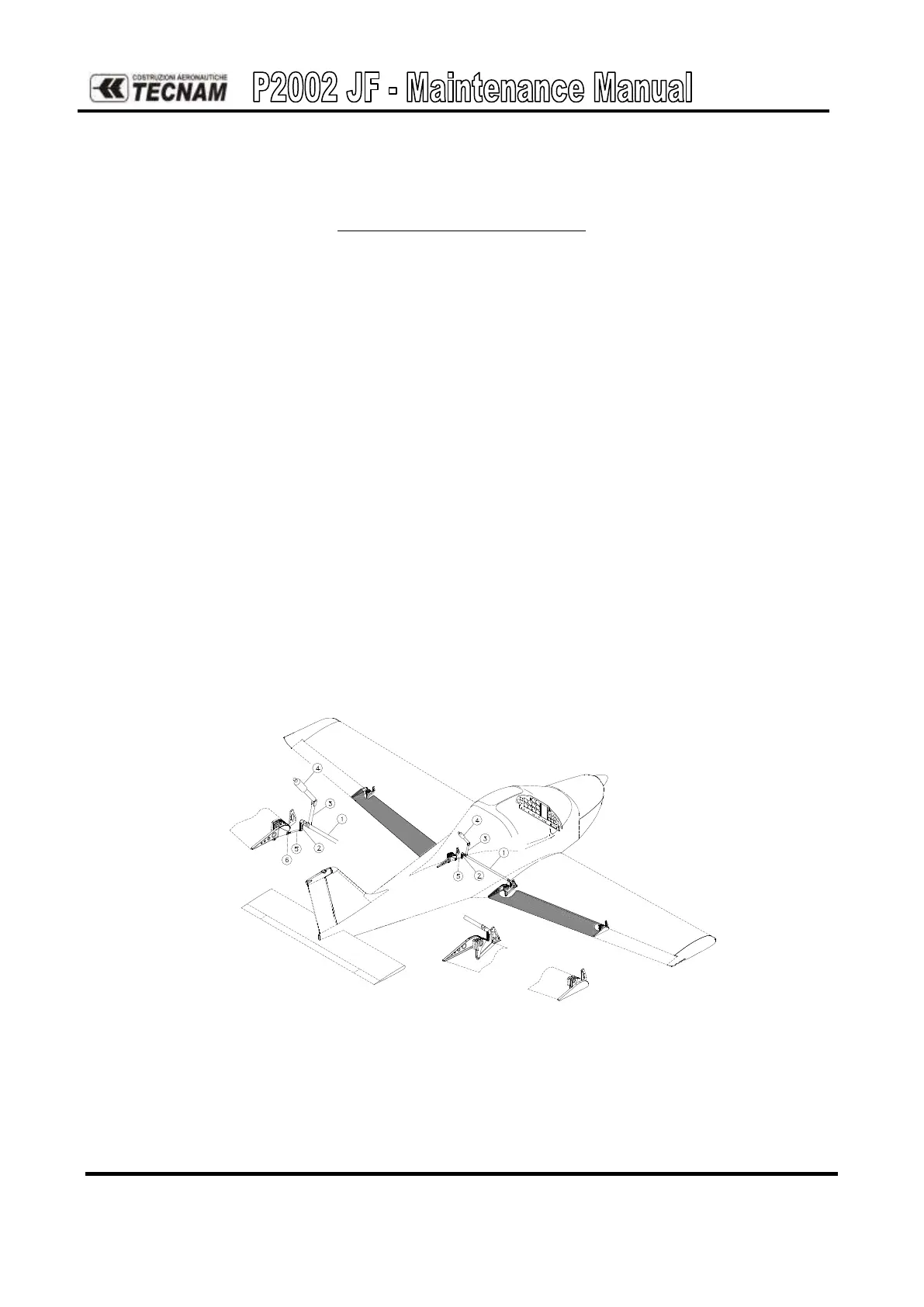
Flap control system is push-pull type. The torque tube (1) is hinged to the cabin truss and
connects the two moving surfaces by two levers (2). An electric linear actuator (4) governed
by a switch on instrument panel controls the torque tube movements via a lever (3).
Two push-pull rods (5) are connected to the ends of the torque tube (1) and are located in the
area between wing and fuselage thus facilitating inspection.
The two push-pull rods controlling flap movement feature an adjustable linkage just before
the roller bearings allowing trailing edge alignment.
Figure 15a. – Flap control
The flaps position indicator is provided on the instruments panel: see Chapter 31.