Page 10 2
nd
Edition – Rev 0
03-00
AIRPLANE GENERAL DESCRIPTION
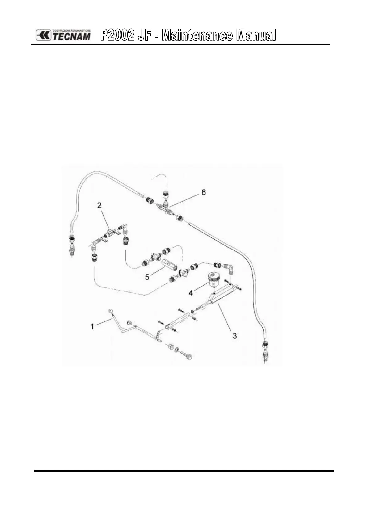
Brake System
Wheels feature hydraulically actuated disc brakes (see Figure 10) controlled by a lever (1)
located on cabin tunnel between seats. Main gear wheels mount Air Trac type 5.00-5 tires
inflated at 23 psi (1.6 bar). Hydraulic circuit shut-off valve (2) is positioned between seats.
With circuit shut off, pulling emergency brake lever activates parking brake function.
Braking is simultaneous on both wheels (via a “T” shaped joint (6)).
Control lever (1) activates master cylinder (3) that features built-in brake-fluid reservoir (4).
The brake system is equipped with a non-return valve (5), which insures that braking action is
always effective even if parking brake circuit should accidentally be closed.
Figure 10: Brake system layout (Standard)