Page 204 2
nd
Edition – Rev 0
55-10
STABILATOR – DESCRIPTION AND OPERATION
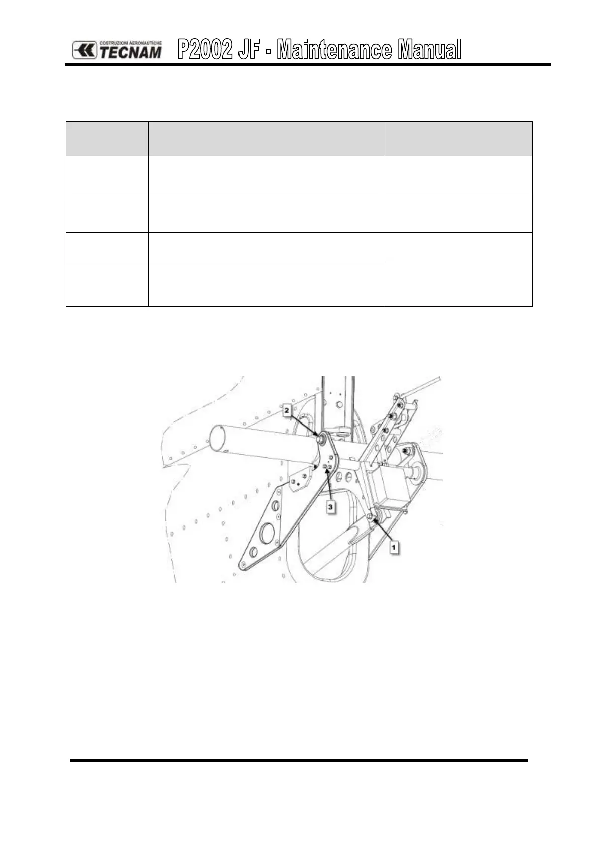
To remove stabilator’s torque tube perform the procedure below
Additional info &
References
Disconnect the connector of electric actuator
stabilator trim tab
Disconnect the stabialtor control rod from
torque tube assy
Remove the trim actuator support attachments
(LH and RH side), by removing 6 bolts
Unscrew the bolts, which fix the torque tube
to stabilator mounting plates and remove the
torque tube
Reverse procedure for reinstallation, setting the torque value according to AMM ATA20 and
applying a small amount of grease on connections.
Figure 9. – Stabilator torque tube assy
NOTE: During the 100 hours inspection of the integrity and bearing cap play of the
stabilator attachments, following the inspection list reported in ATA 5, if an excessive play
between the torque tube and the stabilator support plate is found, it is recommended to add a
washer between one of the support mounting plate and the torque tube bracket