Page 4 2
nd
Edition - Rev 0
75-10
LIQUID COOLING SYSTEM – DESCRIPTION AND OPERATION
Figure 2. shows an optional configuration available with a thermostatic valve which
regulates coolant flow through the radiator.
The system has been realized accordingly to manufacturer’s requirements and it must be
able to supply engine with a proper quantity of coolant (55 lt/min) at temperatures not
above the maximum allowable (135°C).
The thermostatic valve, provided with two thermal sensors, allows an automatic adjust-
ment of temperature by controlling coolant flow to radiator and keeping it at tempera-
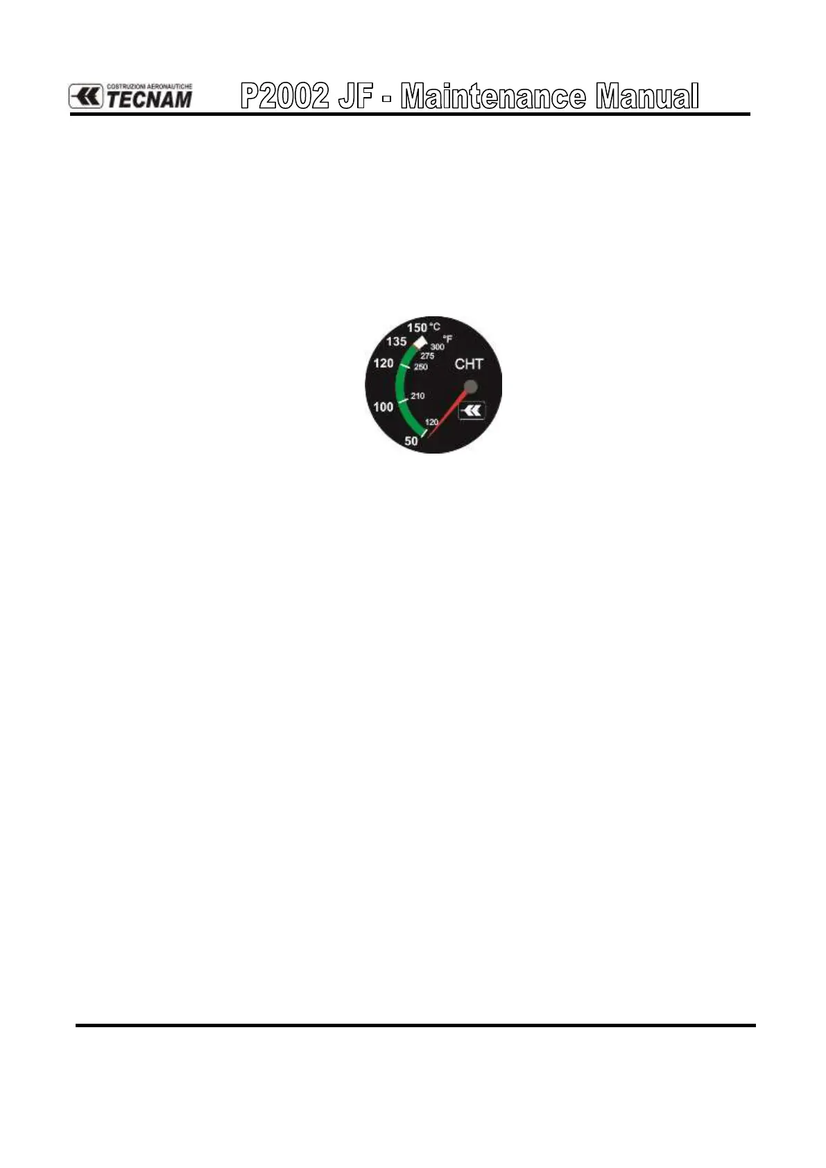
tures between 50°C and 135°C (green arch on CHT indicator).
Figure 3: CHT indicator
Thermostatic valve’s functioning is described below.
Coolant temperature below 90°C;
The scheme in figure 4 shows coolant flow at T<90°C. The coolant in the overflow bot-
tle is sucked in the circuit.
Before it reaches the pump, the coolant passes through the thermostatic valve whose
thermal sensors, at temperatures below 90°C, deny access to radiator.
Once reached the pump, coolant is transferred to cooling circuit and, then, to the over-
flow bottle.