Page 2 2
nd
Edition – Rev 0
32-20
BRAKE SYSTEM – DESCRIPTION AND OPERATION
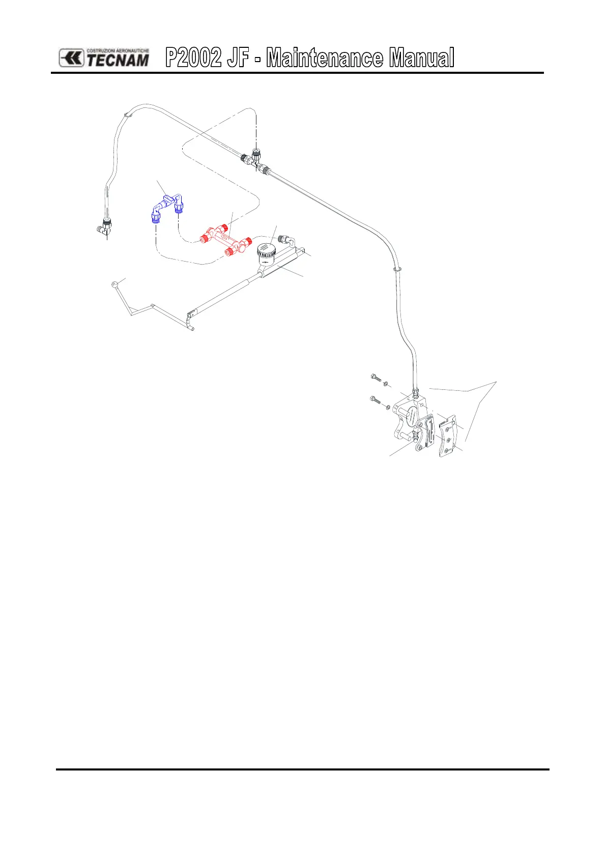
Figure 16. – Lever brake system
TOE BRAKE SYSTEM
The toe brake system consists of independent hydraulically actuated brake system for each
main wheel. A master cylinder is attached to each pilot’s rudder pedal (see Figure 36 below).
Hydraulic pressure, applied via the master cylinders, enters the brake via lines connected to an
inlet fitting on the caliper. The caliper operation description is given on Chapter 32-10.
A parking brake valve, mounted in correspondence of the cabin floor and operated by a knob
on the cockpit central pedestal, intercepts the hydraulic lines, once pressurized by toe brakes,
to hold the brake assemblies linings tightened round the main wheels brake discs.
Brakes can be operated from either pilot’s and co-pilot’s pedals: a single vented oil reservoir
feeds the pilot side master cylinders which are connected, via hoses, with the co-pilot’s side
ones (see system schematic reported on 17).