Page 1 2
nd
Edition – Rev 0
53-10
FUSELAGE – DESCRIPTION AND OPERATION
53-10 FUSELAGE
DESCRIPTION AND OPERATION
The front part of the fuselage is made up of a mixed structure: a truss structure with
special steel members for cabin survival cell, and a light-alloy semi-monocoque
structure for the cabin's bottom section.
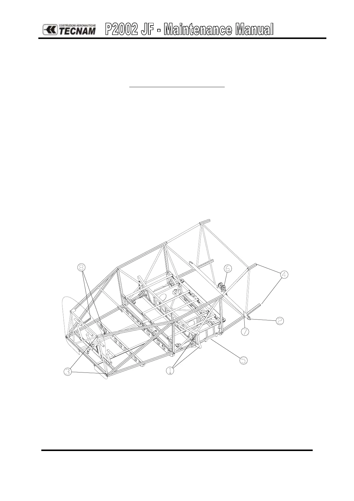
Forward truss structure drawing shows location of attachment points for wing’s main
spar (1), wing’s rear spar (2). tail cone (4), main landing gear (5), engine mount (3), flap
torque tube (7), stabilator bellcrank (6), throttle support (8) and pulley support for cable
driven aileron control. Seat supports and safety harness attachment points are also
shown.
The aft part of the fuselage is constructed with an aluminum alloy semi-monocoque
structure. Attachments to cabin truss is at the forward fittings of four stringers (1). Two
flanges are located at the aft end of the tail section to support the horizontal tail assy (2)
and the vertical tail forward and aft spars (3).
Figure 1. – Cabin truss