Page 2 2
nd
Edition - Rev 0
57 -10
WINGS – DESCRIPTION AND OPERATIONS
57-10 WINGS
DESCRIPTION AND OPERATION
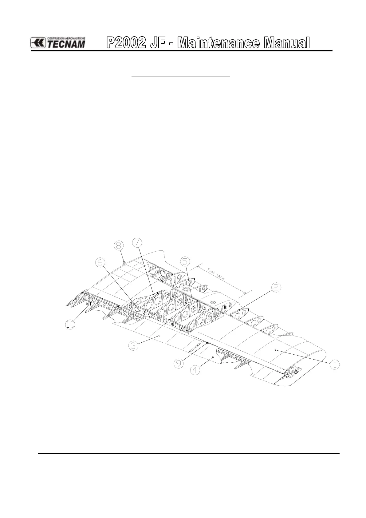
Each wing is connected to the fuselage by means of three pins attachment.
Wings are made up of a central light alloy torsion box (1); an aluminum alloy leading
edge (2) is attached to the front (main) spar (5), while flap (3) and aileron (4) are at-
tached to rear (fake) spar (6) through two hinges each.
The torsion box, as shown in Figure 1. and with reference to numbers in parenthesis,
consists of a main spar (5) and a rear spar (6) that make up its front and rear vertical
walls; a series of ribs (7) and wrap-around panels complete the structure. Front and aft
spars are complete with wing-to-fuselage attachment fittings (8). An integral fuel tank
is a part of the wing’s leading edge. It feature two inspection panels at its root and tip
side. On the upper side of each tank there are the filler cap and the fuel level sensor’s
access door. On the lower side a drainage tap is present. Fuel tank vents by means of a
tube exhausting in the wing tip’s trailing edge.
Aileron uses "piano-hinges" for direct attachment of aileron spar to wing spar. Flap
hinges are external to wing torsion box and feature ball bearings.
Figure 1. - Wing