SUPPLEMENT S1
Chapter 31 – Indicating System
CHAPTER 31 – INDICATING SYSTEM
The aluminium instrument panel is sub-divided in three distinct areas: The left area
holds flight instruments, the right area holds engine controls and the central area can
holds Nav/Com instruments (if installed).
In addition the Aircraft embodying this design change will have installed only
their electrical Indicator, listed below:
Attitude indicator
Directional gyro indicator – (only on analogic instrument panel version)
The related vacuum indicator is consequently removed.
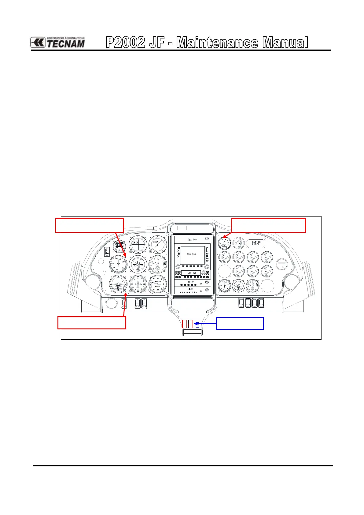
The propeller control line is realized with bowden cables. The following figures
show samples of analogic and digital instrument panels highlighting the propel-
ler control located on the central pedestal:
10
11
12 13 14
17 18
21 22 23
Fuel
pres
Amp
Volt
1
2
3
4
5
6
7
8
9
15
16
19
20
24
25
26
P2002JF Analogic instrument panel
Manifold pressure indica-
tor
Electric Attitude indica-
tor
Electric Directional gyro