FITTING INSTRUCTIONS TEEJET 5000 OPERATORS MANUAL
12.14
BREAK-AWAY PLUG CONNECTIONS
As there are only 7 pins in the breakaway plug and there many different possible
sensor connections, each pin in the plug has a different function depending on
which implement is being used.
The following describes how each sensor should be connected for each individual
implement.
If one of TeeJet Technologies complete implement kits is used, then the correct
connections are taken into consideration and the sensors need only be connected
as shown in the fitting instructions for the implement.
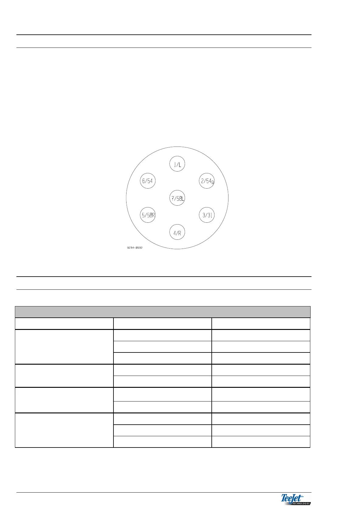
Breakaway plug for the implement seen from the fitting side.
SPRAYER
SPRAYER
SENSOR WIRE COLOUR PIN NUMBER
BLUE 5
FLOWMETER BROWN 2
BLACK 6
SPEED SENSOR BLUE 4
BROWN 5
IMPLEMENT SENSOR
BLUE 7
BROWN 5
BLUE 6
PRESSURE SENSOR BROWN 5
BLACK 1