TEEJET 5000 OPERATORS MANUAL FITTING INSTRUCTIONS
12.13
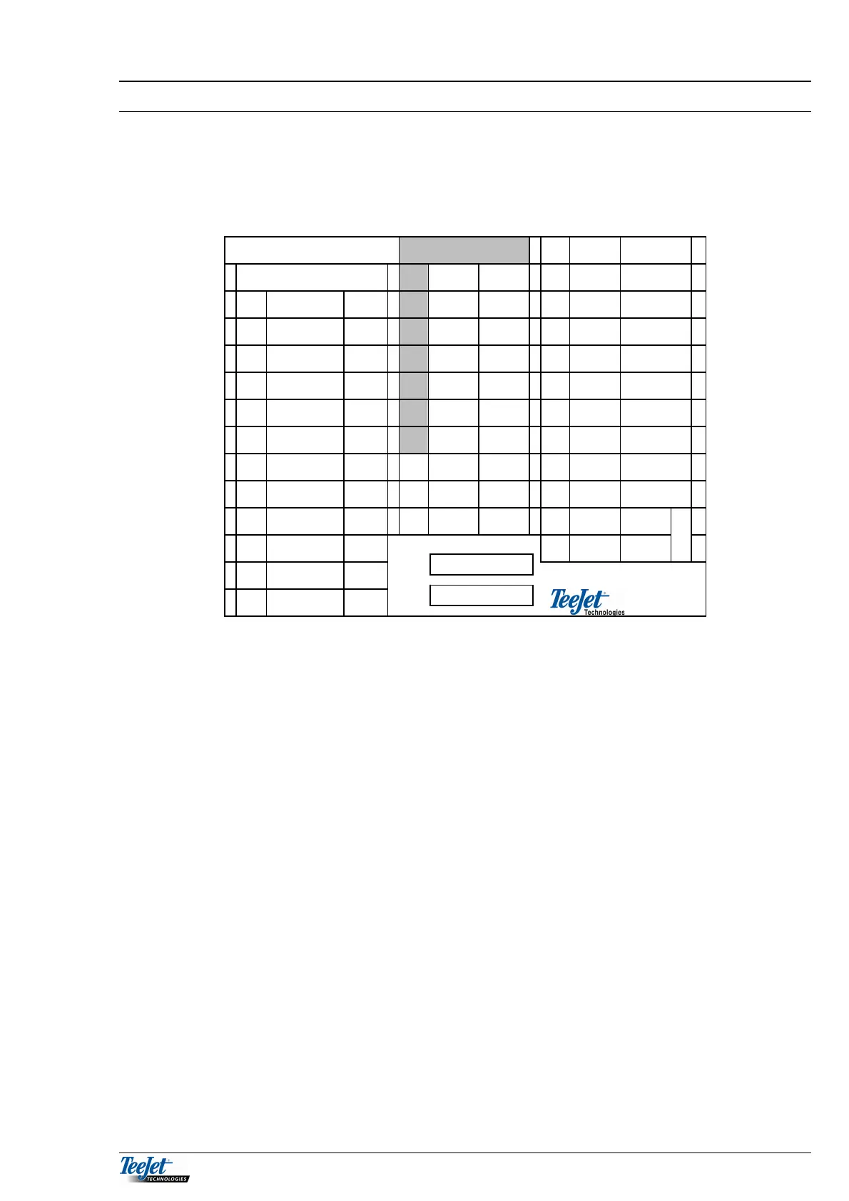
CONNECTIONS IN THE JUNCTION BOX
A label is supplied in the fitting kit, attach this label to the lid of the junction box
to ensure that the connections are always available when/if the system is added to
at a future date.
1 2 3
Break-away plug 1 Blue Diesel
TeeJet 5000
1 White Trail 1 2 Brown 0 V
1 Grey Trail 1 2 Brown Trail 2 3 Blue Implement
2 Red Trail 2 3 Green Mot. 1+ 4 Brown 0 V
3 Brown Mot.
1+
4 Yellow Trail 4 5 Blue + 12 V
4 Yellow Trail 4 5 Grey 0 V 6 Black PTO
5 Blue Imple
ment
6 Pink + 12V 7 Brown 0 V
6 Pink Diesel 7 Blue Trail 7 8 + 12 V
7 Green Trail 7 8 Red + 12V 9 Blue Wheel
8 Violet PTO 9 Green Radar 10 Brown 0 V
9 Black Radar 10 Black
Blue
0 V 11 Blue + 12 V
10 Grey/Pink Wheel 12 Brown 0 V
P
o
e
11 White +12V
12 Blue/Red
White/Green
0V
MULTI-CABLE FROM THE TEEJET 5000
Connect this cable to connecting block 1. Connect the individual wires according
to the colour code on the label.
MULTI-CABLE FROM THE BREAK-AWAY PLUG
Connect to connecting block 2 (1-7) according to the colour code on the label.
DIESEL FLOWMETER
Connect to connecting block 3 (1-2) according to the colour code on the label.
RADAR
Connect to connecting block 2 (8-10) according to the colour code on the label.
POWER SUPPLY
Connect to connecting block 3 (11-12) according to the colour code on the label.
IMPLEMENT SENSOR
Connect to connecting block 3 (3-4) according to the colour code on the label.
PTO - SENSOR (RPM)
Connect to connecting block 3 (5-7) according to the colour code on the label.
SPEED SENSOR
Connect to connecting block 3 (8-10) according to the colour code on the label.
FUSE 4
FUSE 4