Step 2
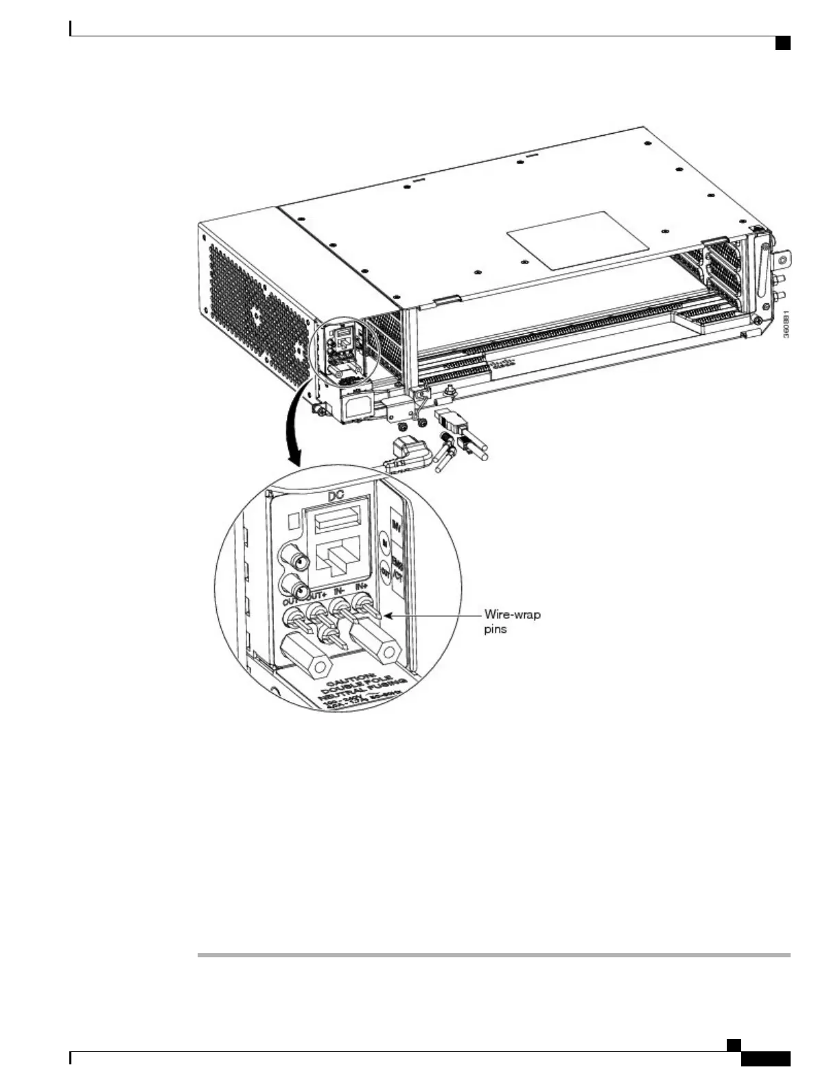
Using a coaxial cable with DIN 1.0/2.3 miniature coax connectors, connect the clock cable to the appropriate
connector in the Power Module.
Step 3
Gently push the cable with the DIN 1.0/2.3 miniature coax connector down until the cable connector slides
into the DIN 1.0/2.3 miniature coax connector on the Power Module with a click. The Power Module provides
DIN 1.0/2.3 miniature coax connectors that are used for timing input and output. The input connectors for
timing provide a 75-ohm termination. System cables that can convert timing clocks from 75 ohms to 100/120
ohms are available.
See ITU-T G.813 for rules about provisioning timing references.Note
Step 4
Connect the other end of the cable to the external source of the timing.
Repeat this step for each cable that is needed.
Step 5
Return to your originating procedure (NTP).
Cisco NCS 2000 Series Hardware Installation Guide
101
Connecting and Routing the Cables and Wires
DLP-L55 Installing Timing Wires in Cisco NCS 2002- ETSI