Table 15: ECU module Pin Assignments - ANSI
FunctionPin
Input from external driveIN 1
Output to external driveOUT 1
Input from external driveIN 2
Output to external driveOUT 2
Step 2
Connect one end of the wire-wrap clock cable to the corresponding wire-wrap connector on the ECU module,
and the other end to the external source of the timing. Change the timing input to high-impedance (lesser or
greater than 3 ohms) using a jumper on the ECU module. Remove the P1 jumper of the BITS-1 to change the
top timing input, and the P2 Jumper of the BITS-2 to change the bottom timing input.
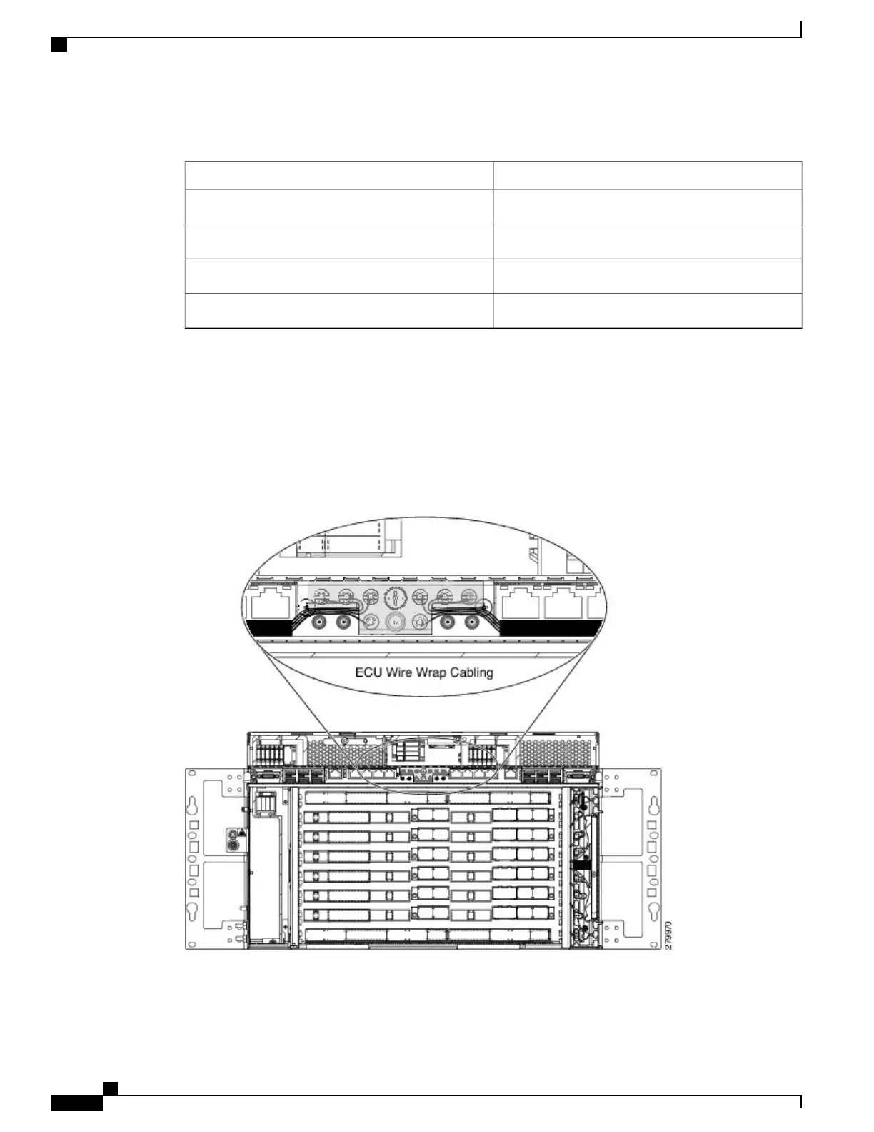
Route the wire-wrap connections as shown in the figure below to prevent interference with the MSM
ports.
Note
Figure 137: ECU module Wire-wrap Cabling
—
ANSI
Cisco NCS 2000 Series Hardware Installation Guide
236
Connecting and Routing the Cables
DLP-L27 Installing Timing Wires on NCS 2006 - ANSI