Step 2
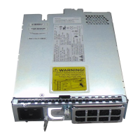
Plug the DC power module completely into the chassis.
Step 3
Tighten the screw to a torque value of 4 in-lb (0.45 N-m) to lock the power module in the chassis (see Figure
4-30).
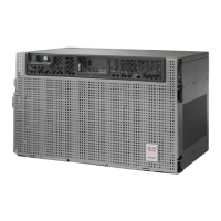
Figure 171: DC Power Modules Installed in the NCS 2006 Shelf
For redundant power supplies, two DC power modules can be installed in Slot A and Slot B. However,
only one power module can sustain the functioning of the entire NCS 2006 system. In that case, insert
a power filler module in the empty slot.
Note
Cisco NCS 2000 Series Hardware Installation Guide
288
Installing the Cisco NCS 2006 Door and Other Modules
DLP-L15 Installing the DC Power Module in the NCS 2006 Shelf
 Loading...
