Procedure
Step 1
Verify that the correct fuse and alarm panel is installed.
Step 2
Connect each of the distribution cables according to the fuse panel engineering specifications.
Step 3
Measure and cut the cables as needed to reach the NCS 2015 from the fuse panel.
Step 4
Strip 1/2 inch (12.7 mm) of insulation from all power cables that you will use.
Step 5
Crimp the lugs onto the ends of all the power distribution cables using the manufacturer’s suggested die for
the lug.
Step 6
Remove the terminal block protective covers from the power distribution lugs.
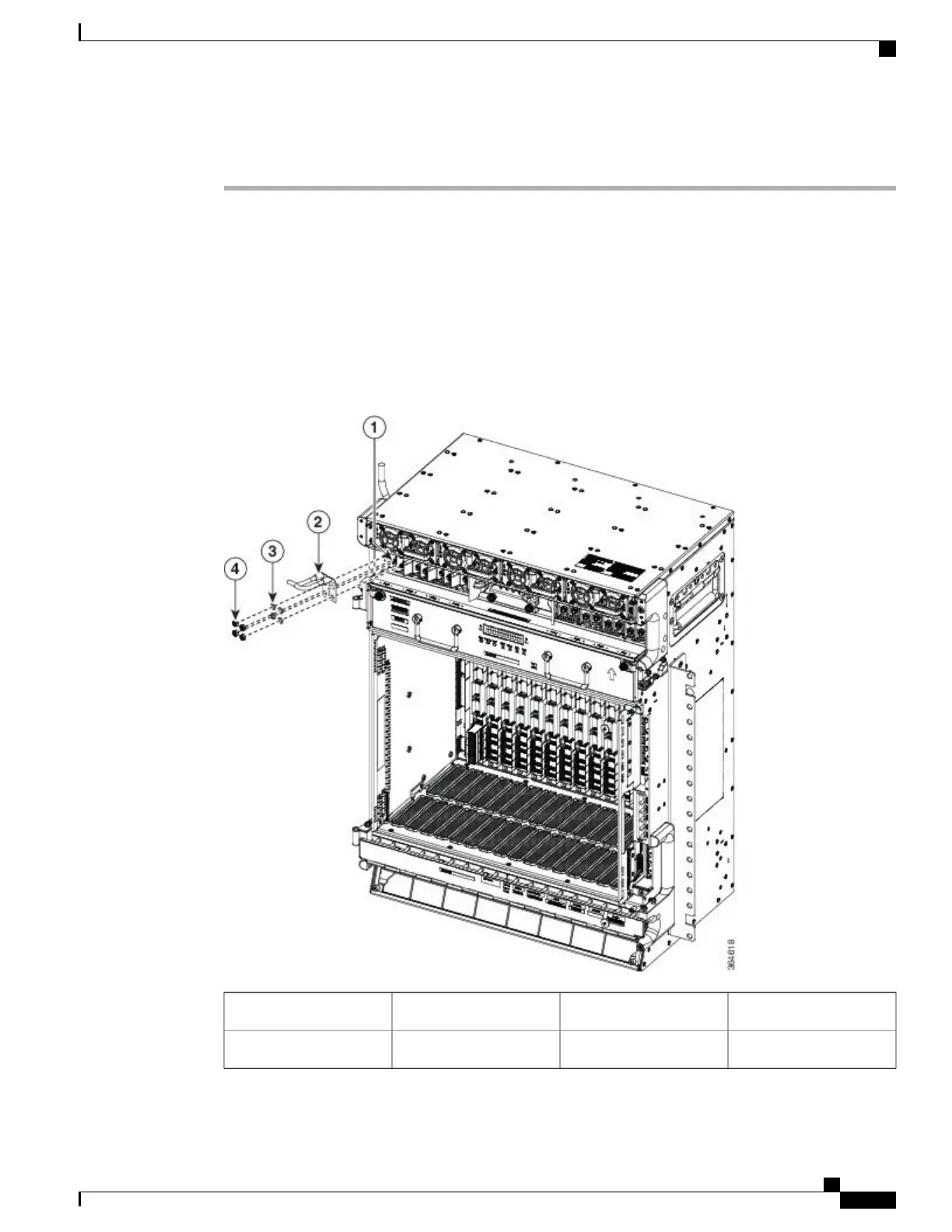
Figure 197: Connecting Office Power
—
DC Power Modules
Power lug2Terminal block1
Nuts4Lock washers3
Cisco NCS 2000 Series Hardware Installation Guide
343
Connecting Power and Ground
DLP-L79 Connecting Office Power (DC) to the NCS 2015 Shelf