Procedure
Step 1
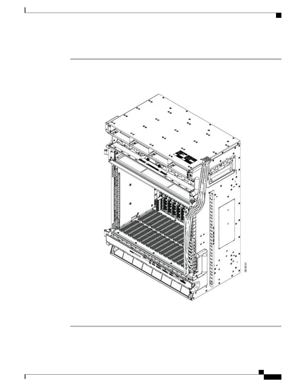
Route the ECU cables on the ECU handle and fix the cables using tie-wrap. The following figure shows an
example of ECU cable routing. This allows you to close the front door.
Figure 200: ECU module Cable Routing in NCS 2015 DC Shelf
Step 2
Route the optical cables from the line cards through the cable module as shown in the figure above.
Stop. You have completed this procedure.
Cisco NCS 2000 Series Hardware Installation Guide
349
Connecting and Routing the Cables
NTP-L55 Routing and Locking Cable and Fiber Modules