Step 2
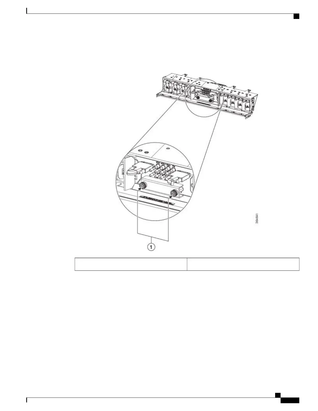
Loosen the screws on the protective cover as shown in the figure below.
Figure 203: Wire-wrap Cabling
Screws1
Step 3
Connect one end of the wire-wrap clock cable to the corresponding wire-wrap connector on the power input
panel and the other end to the external source of the timing. Change the timing input to high-impedance (lesser
or greater than 3 ohms) using a jumper on the power input panel. To change the top timing input, remove the
P1 jumper of the BITS-1, and to change the bottom timing input, remove the P2 Jumper of the BITS-2.
Cisco NCS 2000 Series Hardware Installation Guide
355
Connecting and Routing the Cables
DLP-L77 Installing Timing Wires on NCS 2015