Step 4
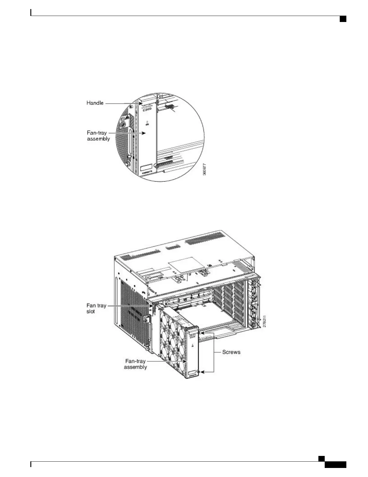
Extract the fan tray partially using the handle in order to disconnect the backplane connector and wait until
the fan stops (see the figure below)
Figure 253: Fan-Tray Assembly Extracted Partially with Power Connector Disconnected
Step 5
When the fans have stopped, pull the fan-tray assembly completely out of the shelf assembly (see the figure
below).
Figure 254: Fan-Tray Extracted
Step 6
Slide the new fan-tray into the shelf assembly until the electrical plug at the rear of the tray plugs into the
corresponding receptacle on the backplane.
Step 7
To verify that the tray has plugged into the backplane, ensure that the LED on the front of the fan-tray is
activated.
Cisco NCS 2000 Series Hardware Installation Guide
459
Maintaining the NCS 2002, NCS 2006, and NCS 2015 Shelves
NTP-L26 Replacing the Fan-Tray Assembly of the NCS 2006 Shelf Assembly