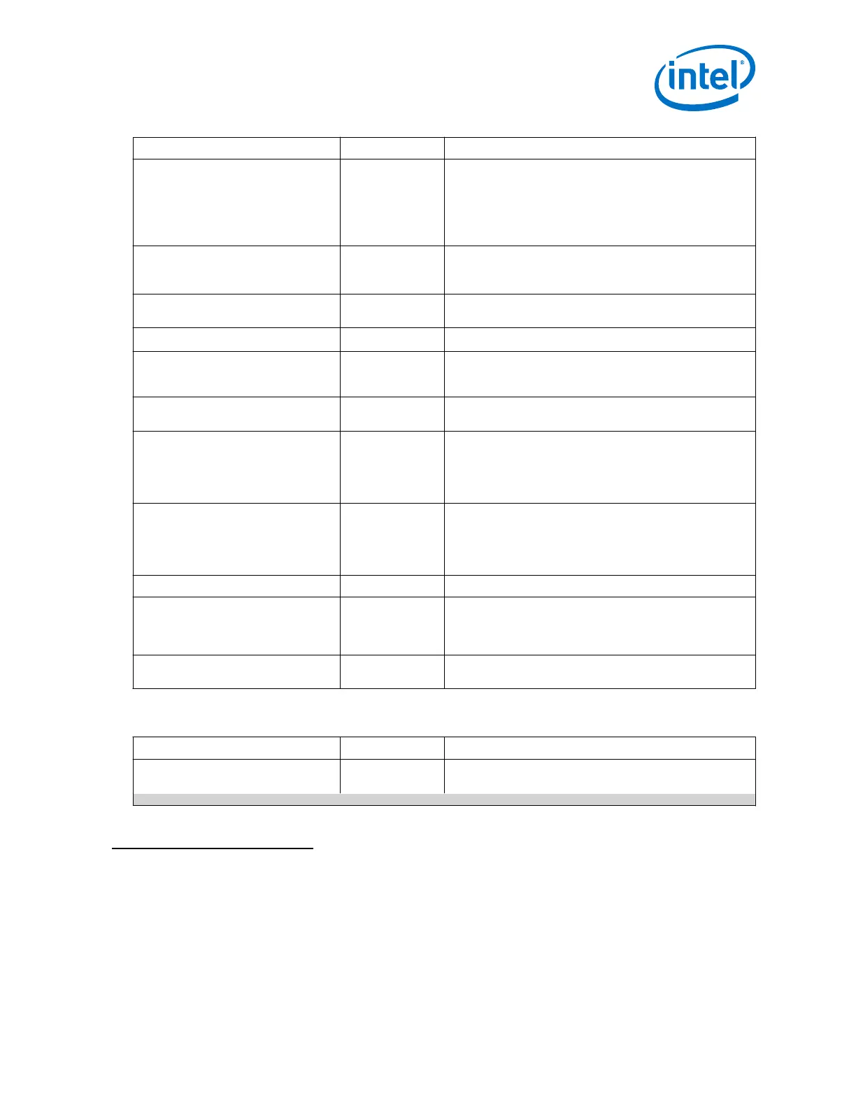
Parameter Range Description
Enable PLL GX clock output port
(51)
On/Off Enables the GX output port which feeds x1 clock lines.
You must select this parameter for PLL output frequency
less than 8.7 GHz, or if you intend to reconfigure the PLL to
a frequency below 8.7 GHz.
Turn ON this port if GX is selected in the "Primary PLL
clock output buffer".
Enable PCIe clock output port On/Off
Exposes the pll_pcie_clk port used for PCI Express.
The port should be connected to the pipe_hclk_input
port.
Enable ATX to FPLL cascade clock
output port
On/Off Enables the ATX to FPLL cascade clock output port.
Enable fref and clklow port
(52)
. On/Off
Enables fref and clklow ports for external lock detector.
PLL output frequency Refer to Intel
Arria 10 Device
Datasheet .
Use this parameter to specify the target output frequency
for the PLL.
PLL integer reference clock
frequency
Refer to the GUI Selects the input reference clock frequency for the PLL.
Multiply factor (M-Counter) Read only
For
OTN_cascade or
SDI_cascade,
refer to the GUI.
Displays the M-counter value.
Specifies the M-counter value (In SDI_cascade or
OTN_cascade Protocol mode only).
Divide factor (N-Counter) Read only
For
SDI_cascade or
OTN_cascade,
refer to the GUI.
Displays the N-counter value.
For SDI_cascade or OTN_cascade, refer to the GUI.
Divide factor (L-Counter) Read only Displays the L-counter value.
Predivide factor (L-Cascade
Predivider)
Refer to the GUI Specifies the L-cascade predivider value. This value must be
2 for a VCO frequency greater than 10.46 GHz and 1 for a
VCO frequency less than 10.46GHz. (In SDI_cascade or
OTN_cascade Protocol mode only).
Fractional multiply factor (K) Read only Displays the actual K-counter value. This parameter is only
available in fractional mode.
Table 230. ATX PLL—Master Clock Generation Block Parameters and Settings
Parameter Range Description
Include Master Clock Generation
Block
(53)
On/Off When enabled, includes a master CGB as a part of the ATX
PLL IP core. The PLL output drives the Master CGB.
continued...
(51)
You can enable both the GX clock output port and the GT clock output port. However, only one
port can be in operation at any given time. You can switch between the two ports using PLL
reconfiguration.
(52)
The fPLL fref and clklow signals should only be used with the Intel external soft lock
detection logic.
(53)
Manually enable the MCGB for bonding applications.
3. PLLs and Clock Networks
UG-01143 | 2018.06.15
Intel
®
Arria
®
10 Transceiver PHY User Guide
355