Keysight M8000 Series of BER Test Solutions User Guide 263
Setting up Generator 5
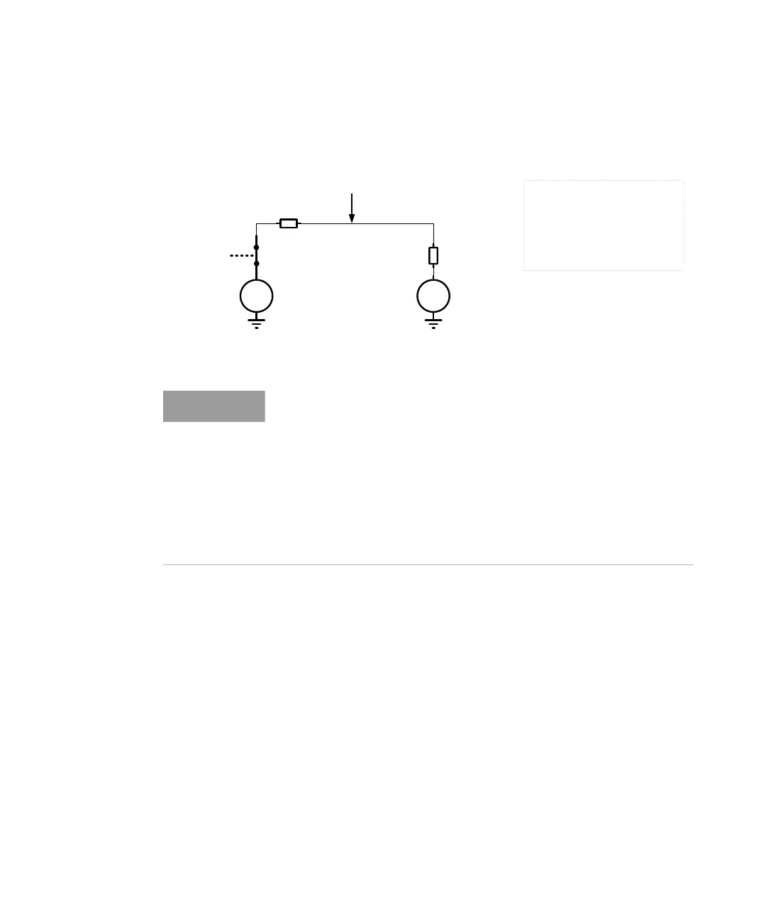
Step 3 If the Measured Voltage = VT + 50 mV −> Pass, turn on the output driver.
VV
Internal 50 Ohm
DUT 50 Ohm
Termination voltage VT
VCCO P = VT +100mV
Closed
Switch
Legends
VT – Termination Voltage
P – Normal (Non-Inverted)
N – Complement (Inverted)
VCCO – Output Voltage Power Supply
DUT – Device Under Test
Measured Voltage = VT +50 mV
→
Pass
In the above diagrams, only normal output is shown. However, the DC
check however is done for normal and complement output. In general,
the both outputs (P/N) need to be terminated the same way.
In single ended use case for better convenience the unused output can
be terminated with 50 Ohm into GND although termination voltage of
used output might not be zero. This is only true as long as the offset
voltage is between +1V and -1V. The mismatch is detected during the
test and is compensated internally. This is implemented in order to make
the termination of unused outputs easier.
 Loading...


