314 Keysight M8000 Series of BER Test Solutions User Guide
6 Setting up Analyzer
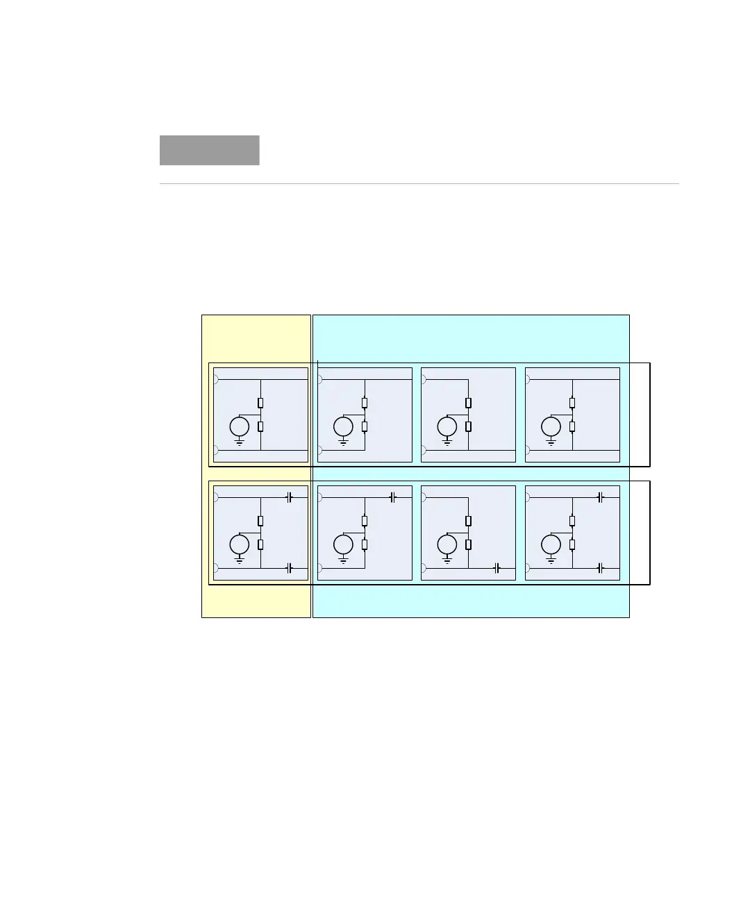
The following drawing is an example how the instrument internal circuitry
looks like for different settings.
This figure is only true for M8041A and M8051A modules with serial
numbers < DE55300500.
This figure shows what the analyzer represents as termination scheme to
the DUT. The DUT would be connected to the connectors shown on the
left part of the respective schemes above.
For the balanced settings the internal termination voltage of the analyzer
is set to equal the Common Mode Voltage, which must be given by the
user in the GUI.
The availability of the particular compare mode selection depends on the
currently used hardware.
VC
VC
VT VT VT
VTVT VT
SE Normal SE Complement Differential
Balanced
Unbalanced
DC
AC
ANALYZER
VT = Termination Voltage
VC = Common Mode Voltage

 Loading...


