EasyManua.ls Logo

Leibinger JET2neo - LEIBINGER JET2 neo Operation Guide; 6.1 Device Construction and Structure

Leibinger JET2neo
294 pages
Print Icon
To Next Page IconTo Next Page
To Previous Page IconTo Previous Page
Loading...
Page 48 Transport/Start up Group 5
Release R1.12 en JET2 neo
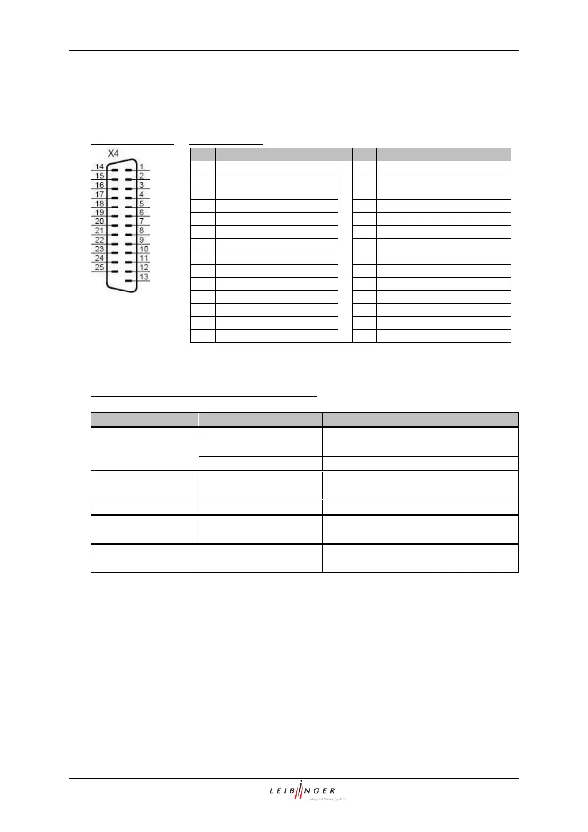
5.5.4 Interface X4 (Inputs)
13 inputs for special functions are available whereof the connections of 3 inputs can be
freely selected.
Plug assignment:
Pin connection:
Basic data /Recommended working conditions:
Signal
Parameter
Value
All signals
Input level High
15 up to 30V
Input level Low
-3,5V up to 3,5V (or high resistance)
Input resistance
6,8kOhm
Increment Counter/
Reset Counter
Minimum pulse width
250µs
Power ON
Minimum pulse width
2,5 s
Jobselect 0-7
Maximum duration
of bounce
10 ms
(2)
Input 1-3
Minimum pulse widths
Depending on assigned function
(see following table)
1)
All 24V ouputs which are designated with (1) are protected by a self-reset fuse with 700 mA.
(2)
For a change of the Jobselect inputs it has to be carried out within the duration of bounce, that means
only after termination of this period of time the new Jobselect No. is validated.
Pin
Designation
Pin
Designation
1
+Reset Counter
14
+24V
(1)
2
+Increment Counter
15
GND Reset Counter /
Increment Counter
3
+Jobselect 0
16
+Jobselect 1
4
+Jobselect 2
17
+Jobselect 3
5
+Jobselect 4
18
+Jobselect 5
6
+Jobselect 6
19
+Jobselect 7
7
20
8
GND Jobselect 0-9
21
GND Input 1-3
9
+Input 1
22
+Input 2
10
+Input 3
23
11
24
12
25
13
GND 24V

Table of Contents

Other manuals for Leibinger JET2neo

Related product manuals