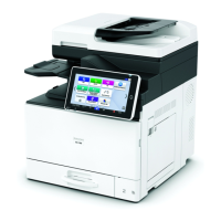
1-Bin Tray BN1040 (D574-59)
D0CA/D0C9/D0C8/D0CB 2-84 SM
14. Route the FFC [A] in step 14 through one ferrite core [B] attached to the control box, and
connect it to the BiCU (PCB1).
• The FFC should be routed under the USB cable.
• Do not connect the FFC at an angle. Otherwise, the scanner unit may be
damaged.
• Connect the scanner FFC for the BiCU (PCB1) while pressing the lock release
button.
15. Attach the following items:
• Hinge cover [A]
• Front right cover [B] (from the accessories, not the original cover)

 Loading...