Process Control and MUSIC
D0CA/D0C9/D0C8/D0CB 7-68 SM
This step adjusts ID sensor’s LED’s light intensity so that Vsg, which is the ID sensor
(S27-S29) output when monitoring the bare surface of the ITB, becomes within 4.0±0.5V.
When Vsg does not reach the target value three times, the machine issues SC370 (ID
sensor Calibration Error).
• SP3-320-011 (Vsg Error Counter)
• SP3-320-013 (Vsg Upper Threshold)
• SP3-320-014 (Vsg Lower Threshold)
• The above SPs can only be accessed from Special Service mode.
This step agitates the developer, and gets the TD sensor output.
The developer agitation time is determined by the three factors below.
1. The change of absolute humidity
2. Non-use time
3. Coverage
Five patterns are created by adjusting the charge/development bias on the transfer belt
for each color. Then the ID sensor (S27-S29) detects the created patterns.
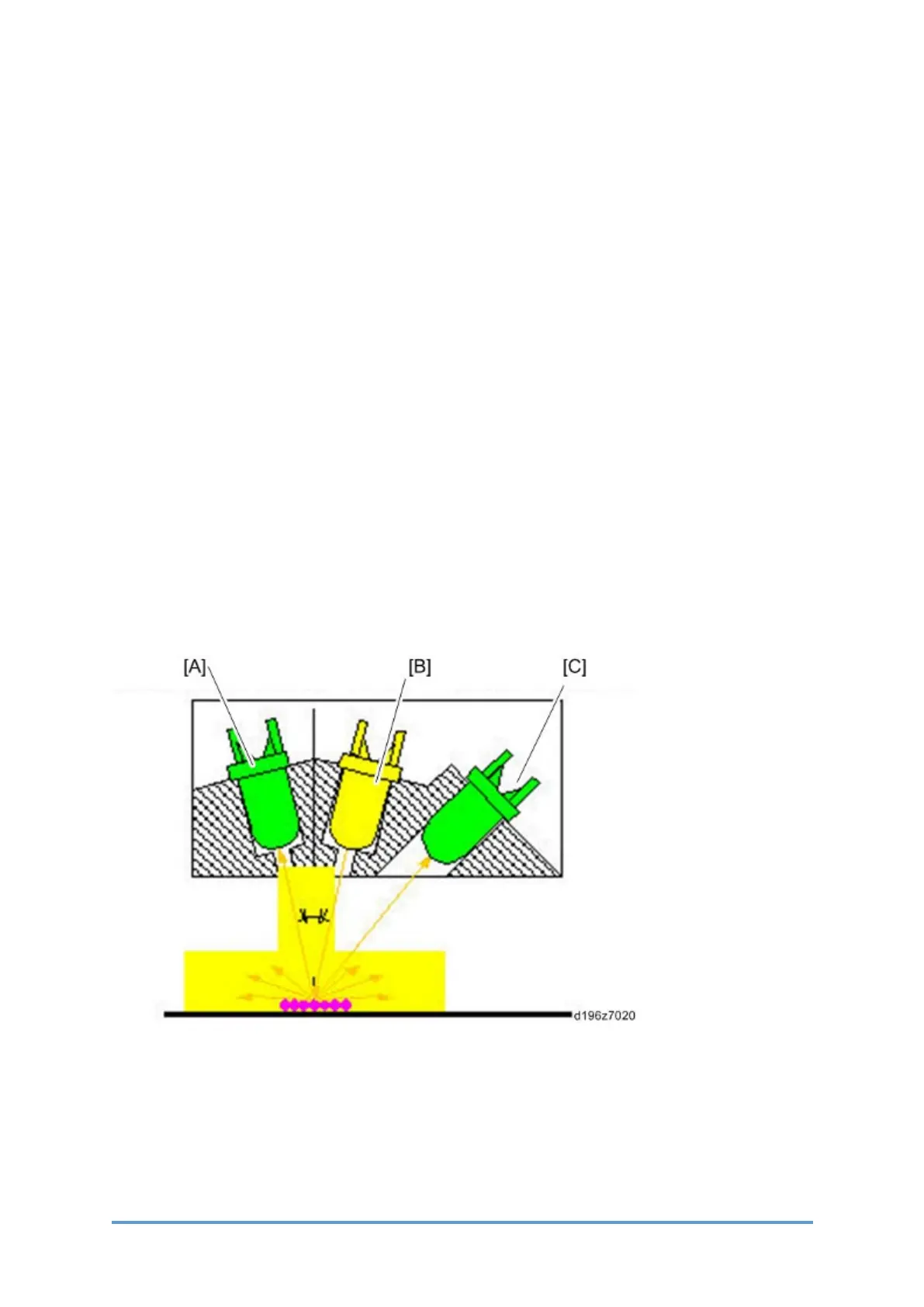
The ID sensor (S27-S29) consists of an LED and two types of photo detector. The sensor
detects the reflection from the LED [B] with the direct reflection detector (REG) [A] and the
diffused reflection detector (DIF) [C].
Detecting the development gamma value with an ID sensor pattern and measuring
Vsp/Vsg determines the charge/development bias for the correct image density.
Also, the reading from the TD sensor (S14-S17) and the development gamma determine Vtref,
which is the reference value for the TD sensor (S14-S17) .
 Loading...