Replacement and Adjustment
D0CA/D0C9/D0C8/D0CB 8-2 SM
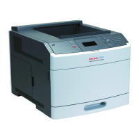
4. Remove the main controller board [A].
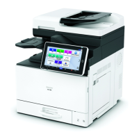
Lift the fastener of the LCD I/F cable [A] on the main controller board side.
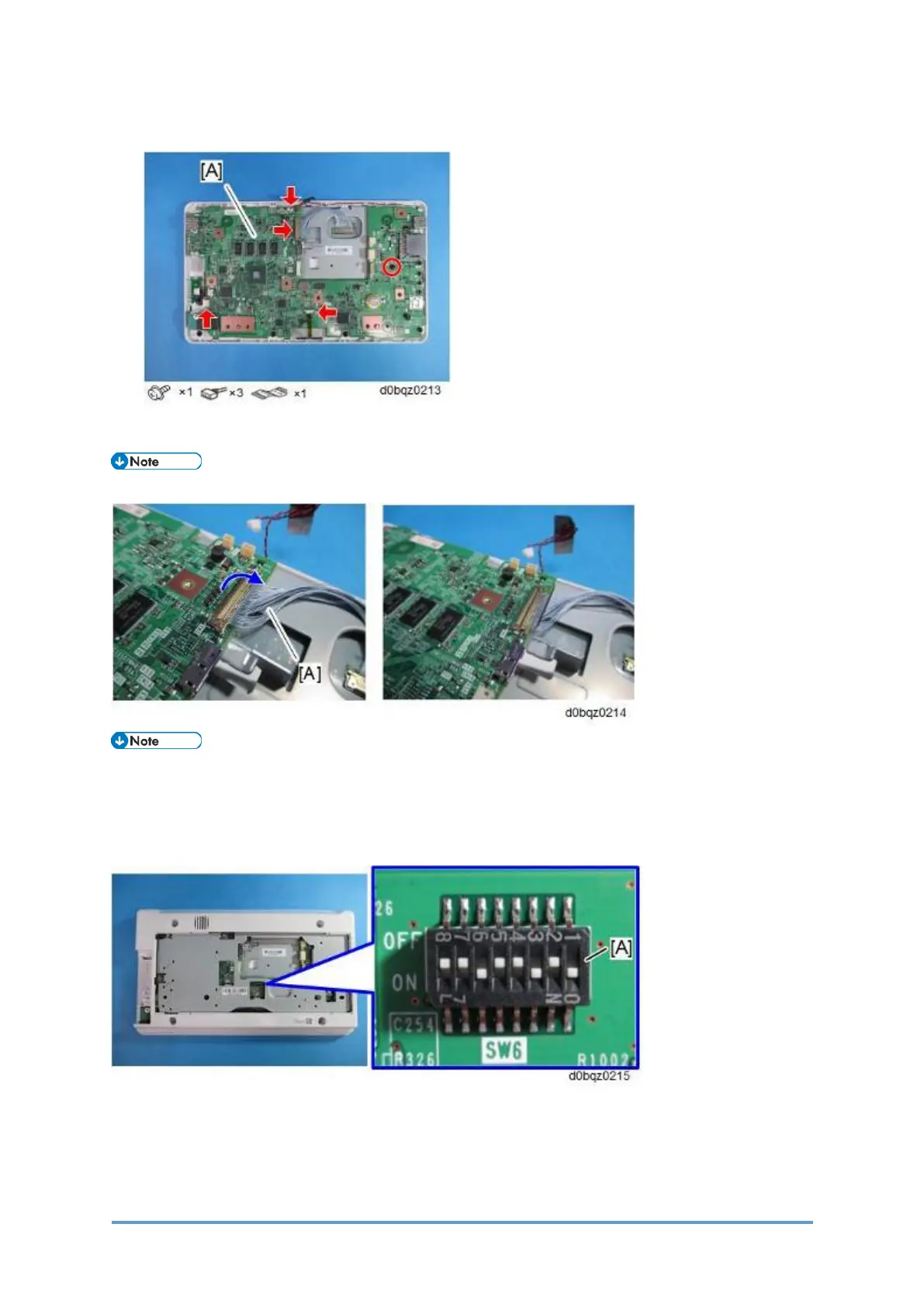
• By factory default, the following switches of the DIP switch [A] on the main controller
board are set to ON: No.1, No.3, and No.6. When installing the operation panel unit,
make sure that the DIP switch setting is correct for the MFP on which you are installing
the panel.
• The correct DIP switch setting depends on the MFP. Note the DIP switch settings of
the old operation panel unit before replacing, and apply the same settings to the new
Smart Operation Panel.
The following example is for DIP switch settings when the following switches are set to
 Loading...