Remote control commands
R&S
®
RTP
2256User Manual 1337.9952.02 ─ 12
●
Chapter 22.3, "Programming examples", on page 1126
● Jitter measurements (option R&S RTP-K12)...................................................... 2256
● Advanced jitter and noise(Option R&S RTP-K133)/(Option R&S RTP-K134).... 2261
● Clock data recovery (software-based, option R&S RTP-K12)............................ 2286
● Eye mask testing.................................................................................................2292
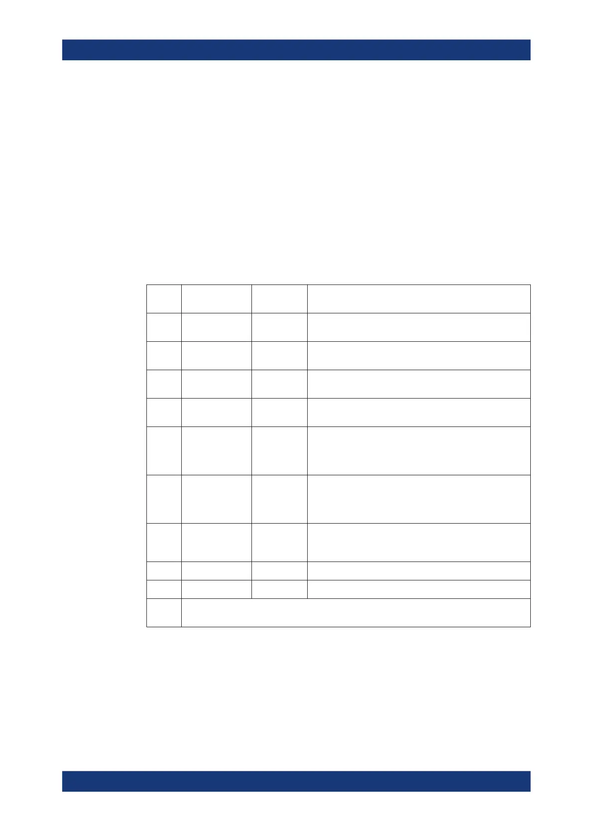
22.22.1 Jitter measurements (option R&S RTP-K12)
The following table lists the measurement suffixes and the <MeasType> parameter
value with a short description.
For a detailed description, see Chapter 18.1.1, "Jitter measurements", on page 1013.
Table 22-19: Jitter measurements
Meas.
suffix
<MeasType>
parameter value
Meas. type Description/Result
37 CCJitter Cycle-cycle
jitter
Difference between the periods of two adjacent cycles. The
measurement is based on the period measurement.
38 NCJitter N-cycle jitter Difference between the time of two adjacent groups of N
cycles (periods) each.
39 CCWidth Cycle-cycle
width
Difference between the pulse width of two adjacent cycles.
The measurement is based on the pulse width measurement.
40 CCDutycycle Cycle-cycle
duty cycle
Difference between the duty cycle of two adjacent cycles.
The measurement is based on the duty cycle measurement.
41 TIE Time interval
error
Time difference between the slope of the input signal and the
slope of a reference signal. The reference signal can be a
captured clock waveform, or a clock generated by clock data
recovery (CDR, software algorithm or hardware generation).
42 UINTerval Unit interval Period of the clock signal. If no clock signal is available, it is
recovered by CDR. The period is calculated as the time dif-
ference between two consecutive clock edges of the same
polarity.
43 DRATe Data rate Frequency of the clock signal. If no clock signal is available, it
is recovered by CDR. The measurement is based on the unit
interval measurement.
44 SKWDelay Skew delay Delay between the edges of two interdependent waveforms.
45 SKWPhase Skew phase Phase difference between the edges of two waveforms.
1 to 36;
46
Used for amplitude/time measurements (limit checks). The jitter category uses the same limit
checks as amplitude/time. See Chapter 22.12.3, "Amplitude/time measurements", on page 1370.
MEASurement<m>:JITTer:CCSLope..............................................................................2257
MEASurement<m>:JITTer:PULSe..................................................................................2257
MEASurement<m>:JITTer:NCYCles...............................................................................2258
MEASurement<m>:JITTer:CDRMode.............................................................................2258
MEASurement<m>:JITTer:SOURce<n>:TIESlope........................................................... 2259
Jitter analysis and clock data recovery

 Loading...


