DMA controller (DMA) RM0008
140/690
DMA2 controller
The 5 requests from the peripherals (TIMx[5,6,7,8], ADC3, SPI/I2S3, UART4,
DAC_Channel[1,2]and SDIO) are simply logically ORed before entering to the DMA2, this
means that only one request must be enabled at a time. Refer to Figure 20: DMA2 request
mapping.
The peripheral DMA requests can be independently activated/de-activated by programming
the DMA control bit in the registers of the corresponding peripheral.
Note: The DMA2 controller and its relative requests are available only in high-density devices.
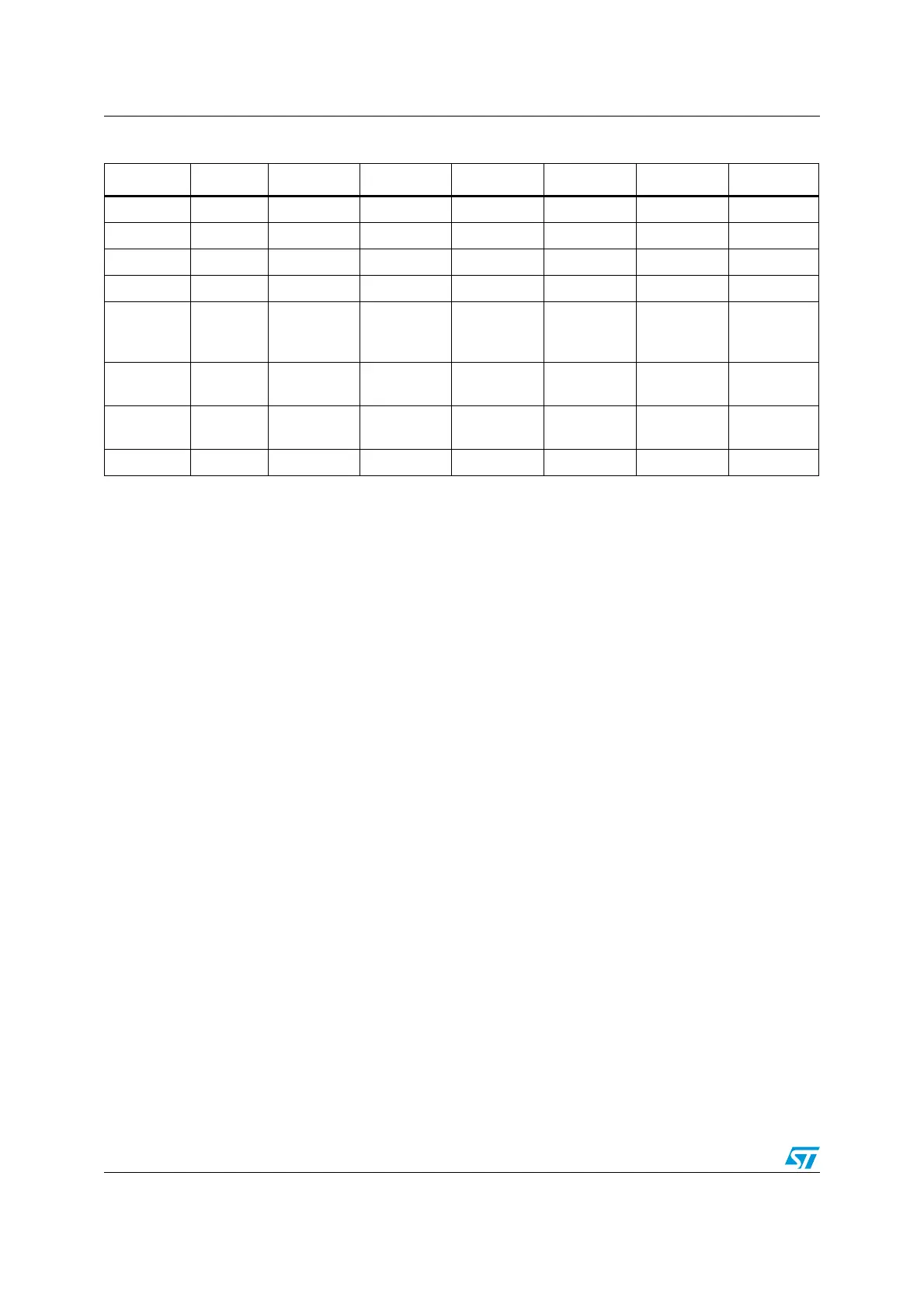
Table 39. Summary of DMA1 requests for each channel
Peripherals Channel 1 Channel 2 Channel 3 Channel 4 Channel 5 Channel 6 Channel 7
ADC1 ADC1
SPI/I
2
S SPI1_RX SPI1_TX SPI/I2S2_RX SPI/I2S2_TX
USART USART3_TX USART3_RX USART1_TX USART1_RX USART2_RX USART2_TX
I
2
C I2C2_TX I2C2_RX I2C1_TX I2C1_RX
TIM1 TIM1_CH1 TIM1_CH2
TIM1_CH4
TIM1_TRIG
TIM1_COM
TIM1_UP TIM1_CH3
TIM2 TIM2_CH3 TIM2_UP TIM2_CH1
TIM2_CH2
TIM2_CH4
TIM3 TIM3_CH3
TIM3_CH4
TIM3_UP
TIM3_CH1
TIM3_TRIG
TIM4 TIM4_CH1 TIM4_CH2 TIM4_CH3 TIM4_UP
 Loading...


