Serial peripheral interface (SPI) RM0008
564/690
22.4.3 Clock generator
The I
2
S bitrate determines the dataflow on the I
2
S data line and the I
2
S clock signal
frequency.
I
2
S bitrate = number of bits per channel × number of channels × sampling audio frequency
For a 16-bit audio, left and right channel, the I
2
S bitrate is calculated as follows:
I
2
S bitrate = 16 × 2 × F
S
It will be: I
2
S bitrate = 32 x 2 x F
S
if the packet length is 32-bit wide.
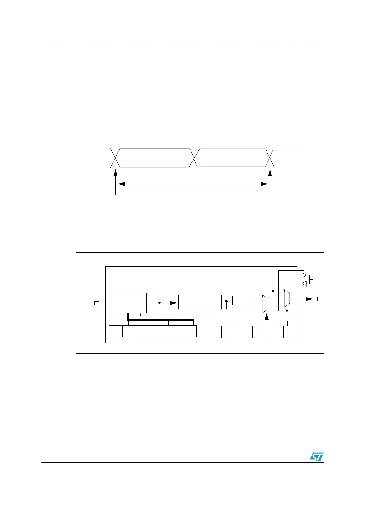
Figure 228. Audio sampling frequency definition
When the master mode is configured, a specific action needs to be taken to properly
program the linear divider in order to communicate with the desired audio frequency.
Figure 229. I
2
S clock generator architecture
1. Where x could be 2 or 3.
Figure 228 presents the communication clock architecture. The I2SxCLK source is the
System Clock (provided by the HSI, the HSE or the PLL and sourcing the AHB clock).
The audio sampling frequency may be 48 kHz, 44.1 kHz, 22.05 kHz, 16 kHz or 8 kHz. In
order to reach the desired frequency, the linear divider needs to be programmed according
to the formulas below:
When the master clock is generated (MCKOE in the SPI_I2SPR register is set):
F
S
= I2SxCLK / [(16*2)*((2*I2SDIV)+ODD)*8)] when the channel frame is 16-bit wide
F
S
= I2SxCLK / [(32*2)*((2*I2SDIV)+ODD)*4)] when the channel frame is 32-bit wide
16-bit or 32-bit Left channel
16-bit or 32-bit Right channel
sampling point
sampling point
32-bits or 64-bits
F
S
F
S
: Audio sampling frequency
8-bit
Divider +
Linear
CK
ODD
I2SDIV[7:0]
I2SxCLK
CHLENI2SMOD
reshaping stage
Divider by 4
Div2
1
0
MCKOE
MCKOE
MCK
0
1
 Loading...


