Analog-to-digital converter (ADC) RM0008
156/690
Example:
n = 1, channels to be converted = 1, 2, 3
1st trigger: channel 1 converted
2nd trigger: channel 2 converted
3rd trigger: channel 3 converted and EOC and JEOC events generated
4th trigger: channel 1
Note: 1 When all injected channels are converted, the next trigger starts the conversion of the first
injected channel. In the example above, the 4th trigger reconverts the 1st injected channel
1.
2 It is not possible to use both auto-injected and discontinuous modes simultaneously.
3 The user must avoid setting discontinuous mode for both regular and injected groups
together. Discontinuous mode must be enabled only for one group conversion.
10.4 Calibration
The ADC has an built-in self calibration mode. Calibration significantly reduces accuracy
errors due to internal capacitor bank variations. During calibration, an error-correction code
(digital word) is calculated for each capacitor, and during all subsequent conversions, the
error contribution of each capacitor is removed using this code.
Calibration is started by setting the CAL bit in the ADC_CR2 register. Once calibration is
over, the CAL bit is reset by hardware and normal conversion can be performed. It is
recommended to calibrate the ADC once at power-on. The calibration codes are stored in
the ADC_DR as soon as the calibration phase ends.
Note: 1 It is recommended to perform a calibration after each power-up.
2 Before starting a calibration the ADC must have been in power-off state (ADON bit = ‘0’) for
at least two ADC clock cycles.
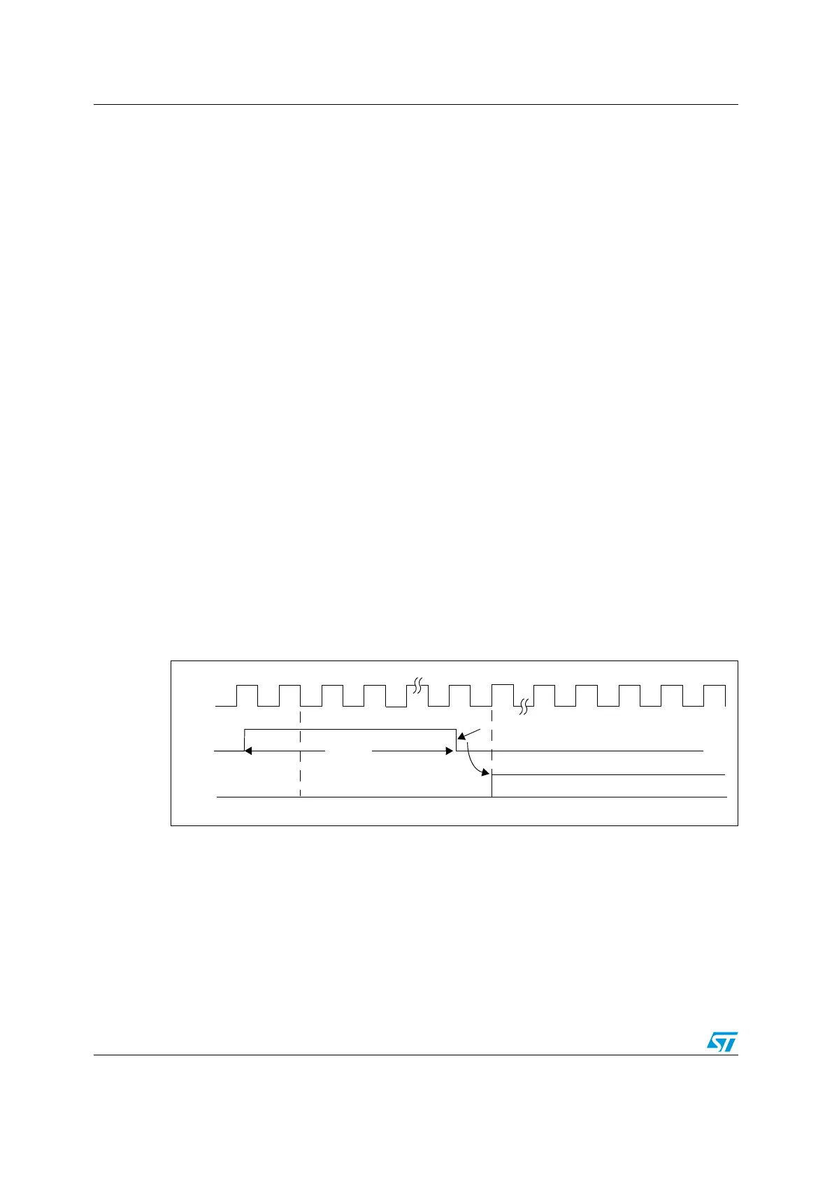
Figure 25. Calibration timing diagram
10.5 Data alignment
ALIGN bit in the ADC_CR2 register selects the alignment of data stored after conversion.
Data can be left or right aligned as shown in Figure 26. and Figure 27.
The injected group channels converted data value is decreased by the user-defined offset
written in the ADC_JOFRx registers so the result can be a negative value. The SEXT bit is
the extended sign value.
For regular group channels no offset is subtracted so only twelve bits are significant.
CLK
t
CAL
Calibration ongoing
CAL
ADC
Conversion
Normal ADC Conversion
Calibration Reset by Hardware
 Loading...


