RM0008 Interrupts and events
123/690
8 Interrupts and events
Medium-density devices are STM32F101xx and STM32F103xx microcontrollers where
the Flash memory density ranges between 32 and 128 Kbytes.
High-density devices are STM32F101xx and STM32F103xx microcontrollers where the
Flash memory density ranges between 256 and 512 Kbytes.
This Section applies to the whole STM32F10xxx family, unless otherwise specified.
8.1 Nested vectored interrupt controller (NVIC)
Features
● 60 maskable interrupt channels (not including the 16 interrupt lines of Cortex™-M3)
● 16 programmable priority levels (4 bits of interrupt priority are used)
● Low-latency exception and interrupt handling
● Power management control
● Implementation of System Control Registers
The NVIC and the processor core interface are closely coupled, which enables low latency
interrupt processing and efficient processing of late arriving interrupts.
All interrupts including the core exceptions are managed by the NVIC. For more information
on exceptions and NVIC programming see Chap 5 Exceptions & Chap 8 Nested Vectored
Interrupt Controller of the ARM Cortex™-M3 Technical Reference Manual.
8.1.1 SysTick calibration value register
The SysTick calibration value is fixed to 9000 which allows the generation of a time base of
1ms with the SysTick clock set to 9 MHz (max HCLK/8).
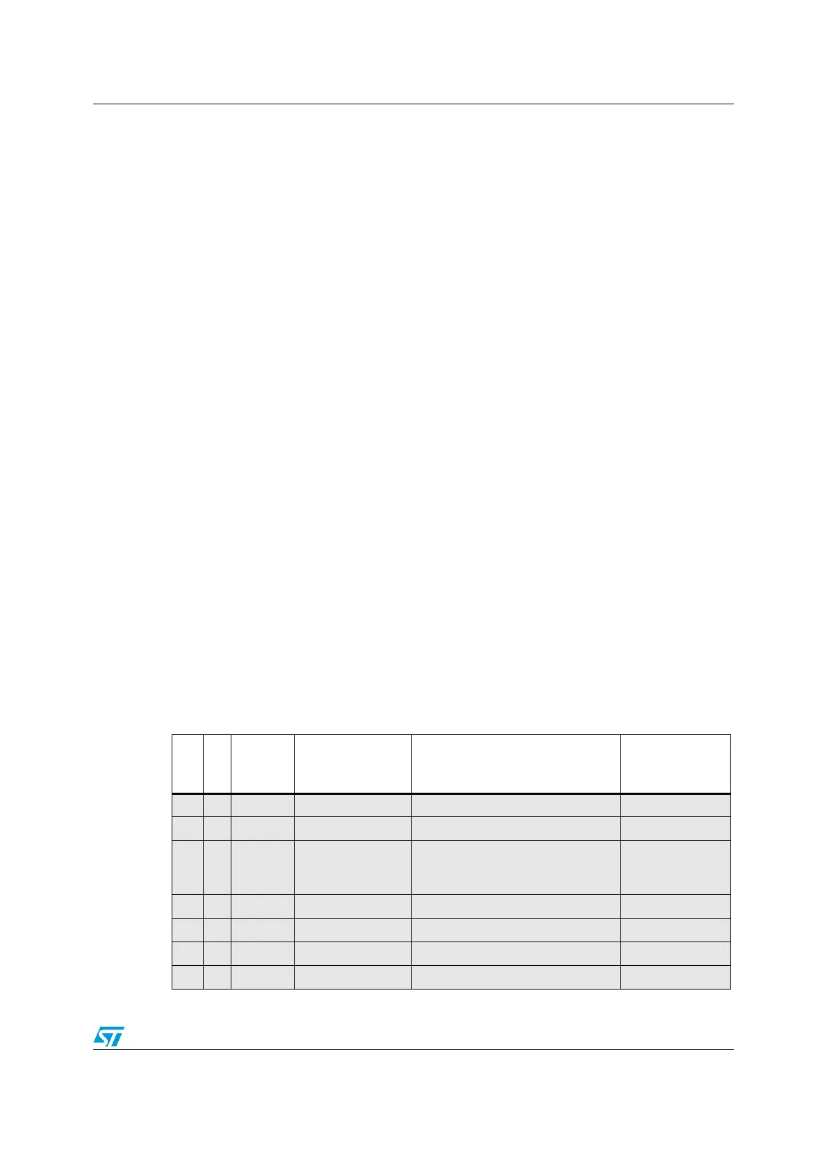
8.1.2 Interrupt and exception vectors
Table 36. Vector table
Position
Priority
Type of
priority
Acronym Description Address
- - - Reserved 0x0000_0000
-3 fixed Reset Reset 0x0000_0004
-2 fixed NMI
Non maskable interrupt. The RCC
Clock Security System (CSS) is
linked to the NMI vector.
0x0000_0008
-1 fixed HardFault All class of fault 0x0000_000C
0 settable MemManage Memory management 0x0000_0010
1 settable BusFault Pre-fetch fault, memory access fault 0x0000_0014
2 settable UsageFault Undefined instruction or illegal state 0x0000_0018
 Loading...


