RM0008 Analog-to-digital converter (ADC)
153/690
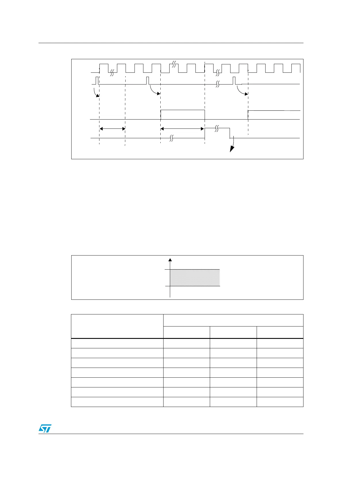
Figure 22. Timing diagram
10.3.7 Analog watchdog
The AWD analog watchdog status bit is set if the analog voltage converted by the ADC is
below a low threshold or above a high threshold. These thresholds are programmed in the
12 least significant bits of the ADC_HTR and ADC_LTR 16-bit registers. An interrupt can be
enabled by using the AWDIE bit in the ADC_CR1 register.
The threshold value is independent of the alignment selected by the ALIGN bit in the
ADC_CR2 register. The comparison is done before the alignment (see Section 10.5).
The analog watchdog can be enabled on one or more channels by configuring the
ADC_CR1 register as shown in Table 43.
Figure 23. Analog watchdog guarded area
ADC_CLK
EOC
Next ADC Conversion
ADC Conversion
Conversion Time
t
STAB
ADC
Software resets EOC bit
SET ADON
ADC power on
(total conv time)
Start 1st conversion
Start next conversion
Table 43. Analog watchdog channel selection
Channels to be guarded by Analog
Watchdog
ADC_CR1 register control bits (x = don’t care)
AWDSGL bit AWDEN bit JAWDEN bit
None x 0 0
All injected channels 0 0 1
All regular channels 0 1 0
All regular and injected channels 0 1 1
Single
(1)
injected channel
1. Selected by AWDCH[4:0] bits
101
Single
(1)
regular channel 1 1 0
Single
(1)
regular or injected channel 1 1 1
Analog voltage
High threshold
Low threshold
Guarded area
HTR
LTR
 Loading...


