RM0008 General-purpose timer (TIMx)
275/690
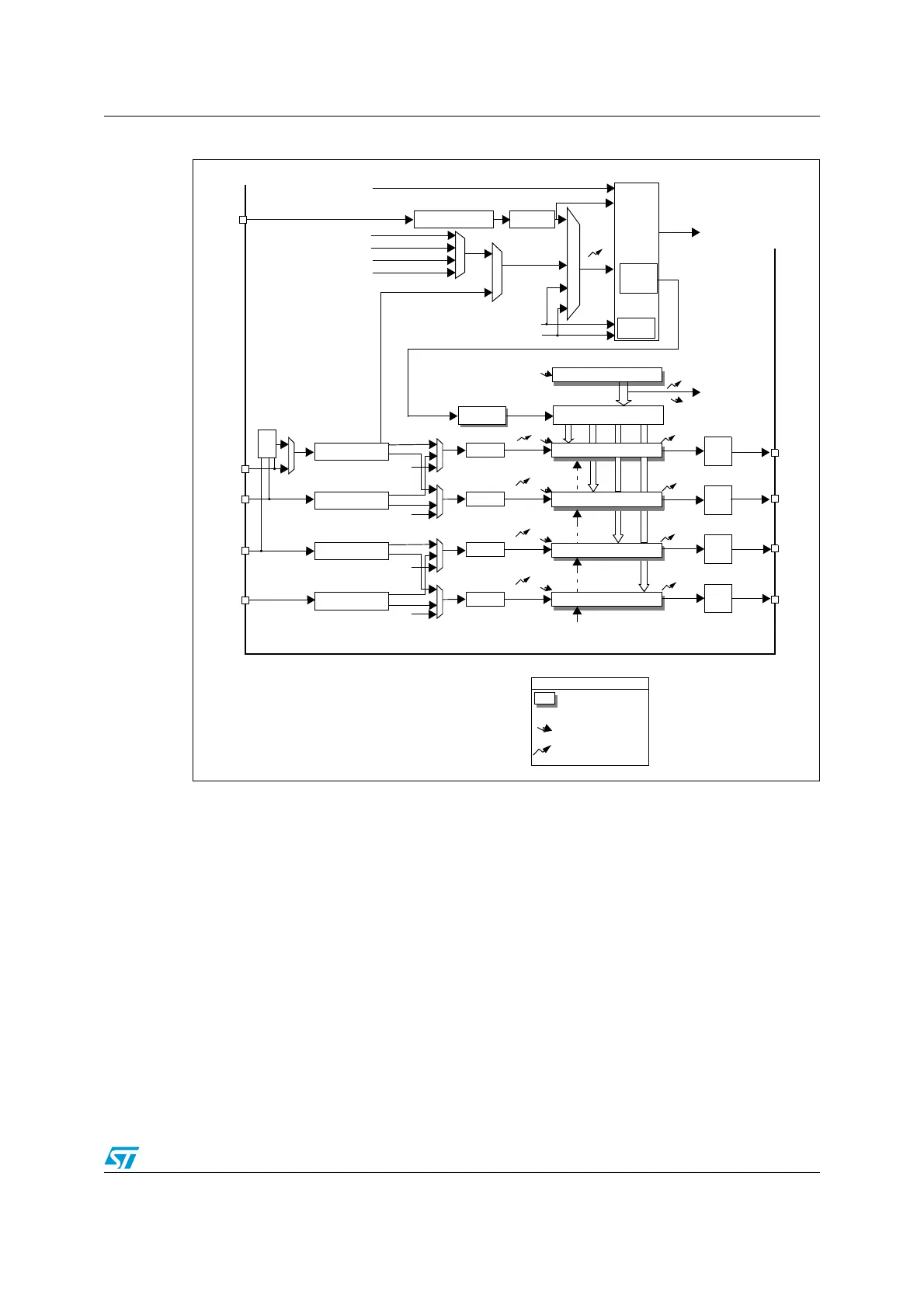
Figure 95. General-purpose timer block diagram
13.3 TIMx functional description
13.3.1 Time-base unit
The main block of the programmable timer is a 16-bit counter with its related auto-reload
register. The counter can count up, down or both up and down. The counter clock can be
divided by a prescaler.
The counter, the auto-reload register and the prescaler register can be written or read by
software. This is true even when the counter is running.
The time-base unit includes:
● Counter Register (TIMx_CNT)
● Prescaler Register (TIMx_PSC):
● Auto-Reload Register (TIMx_ARR)
AutoReload Register
Capture/Compare 1 Register
Capture/Compare 2 Register
U
U
U
CC1I
CC2I
Trigger
Controller
Stop, Clear
or
Up/Down
TI1FP1
TI2FP2
ITR0
ITR1
ITR2
ITR3
TRGI
Encoder
Interface
Capture/Compare 3 Register
U
CC3I
output
control
OC1
TRGO
OC1REF
OC2REF
OC3REF
U
UI
Reset, Enable, Up/Down, Count,
Capture/Compare 4 Register
U
CC4I
OC4REF
Prescaler
Prescaler
IC4PS
IC3PS
IC1
IC2
Prescaler
Prescaler
Input Filter &
Edge Detector
IC2PS
IC1PS
TI1FP1
output
control
OC2
output
control
OC3
output
control
OC4
Reg
event
Notes:
Preload registers transferred
to active registers on
U
event
according to control bit
interrupt & DMA output
TGI
TRC
TRC
IC3
IC4
ITR
TRC
TI1F_ED
Input Filter &
Edge Detector
Input Filter &
Edge Detector
Input Filter &
Edge Detector
CC1I
CC2I
CC3I
CC4I
TI1FP2
TI2FP1
TI2FP2
TI3FP3
TRC
TRC
TI3FP4
TI4FP3
TI4FP4
TI4
TI3
TI1
TI2
XOR
TIMx_CH1
TIMx_CH2
TIMx_CH3
TIMx_CH4
TIMx_CH1
TIMx_CH2
TIMx_CH3
TIMx_CH4
to other timers
TIMxCLK from RCC
Prescaler
COUNTER
+/-
CK_PSC
PSC
CNT
CK_CNT
Controller
Mode
Slave
Internal Clock (CK_INT)
ETR
Input Filter
Polarity Selection & Edge
Detector & Prescaler
ETRP
ETRF
TIMx_ETR
ETRF
to DAC/ADC
 Loading...


