RM0008 Universal synchronous asynchronous receiver transmitter (USART)
635/690
case of single byte reception, there will be separate error flag interrupt enable bit (EIE bit in
the USART_CR3 register), which if set will issue an interrupt after the current byte with
either of these errors.
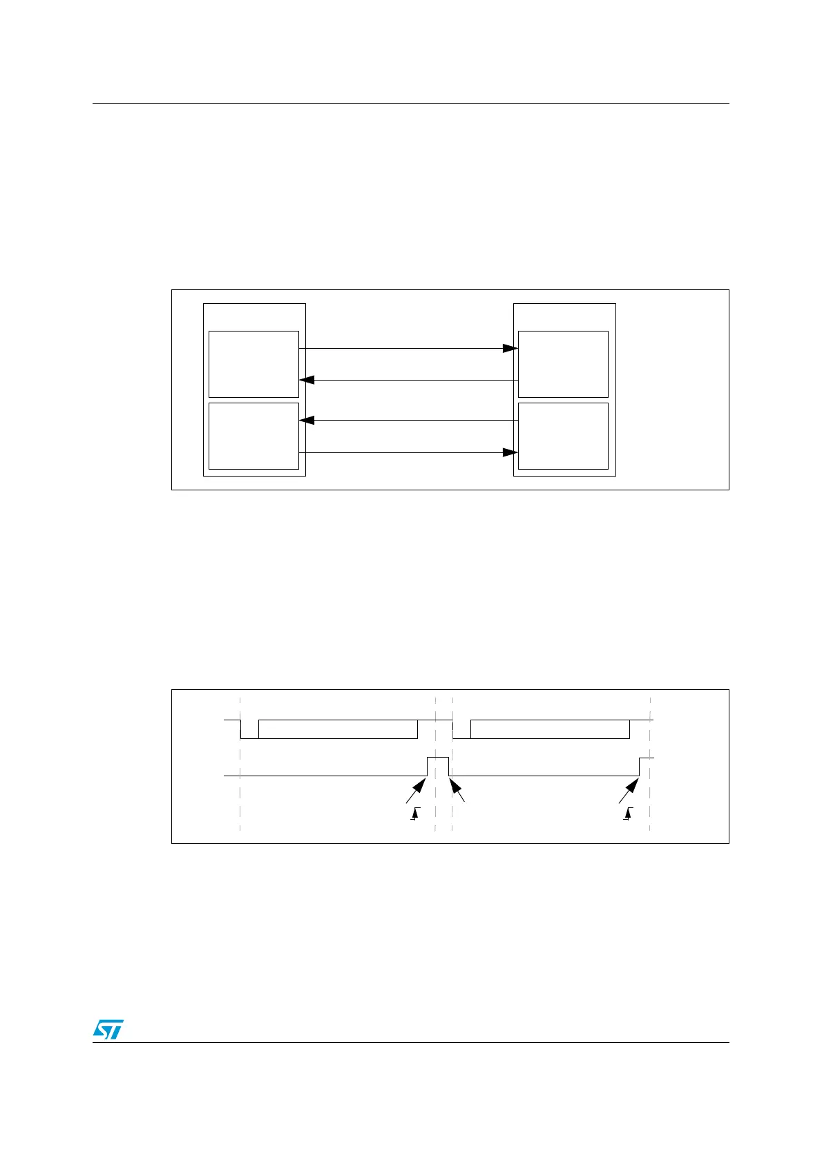
24.3.13 Hardware flow control
It is possible to control the serial data flow between 2 devices by using the nCTS input and
the nRTS output. The Figure 254 shows how to connect 2 devices in this mode:
Figure 254. Hardware flow control between 2 USART
RTS and CTS flow control can be enabled independently by writing respectively RTSE and
CTSE bits to 1 (in the USART_CR3 register).
RTS flow control
If the RTS flow control is enabled (RTSE=1), then nRTS is asserted (tied low) as long as the
USART receiver is ready to receive a new data. When the receive register becomes empty,
nRTS is deasserted, indicating that the transmission is expected to stop at the end of the
current frame. Figure 255 shows an example of communication with RTS flow control
enabled.
Figure 255. RTS flow control
CTS flow control
If the CTS flow control is enabled (CTSE=1), then the transmitter checks the nCTS input
before transmitting the next frame. If nCTS is asserted (tied low), then the next data is
transmitted (assuming that a data is to be transmitted, in other words, if TXE=0), else the
transmission does not occur. When nCTS is deasserted during a transmission, the current
transmission is completed before the transmitter stops.
USART 1
RX circuit
TX circuit
USART 2
TX circuit
RX circuit
RXTX
TX
RX
nCTS nRTS
nRTS
nCTS
Start
Bit
Stop
Bit
Data 1 Idle
Start
Bit
Stop
Bit
Data 2
RX
nRTS
RXNE
Data 1 read
RXNE
Data 2 can now be transmitted
 Loading...


