RM0008 Memory and bus architecture
43/690
2.4 Boot configuration
In the STM32F10xxx, 3 different boot modes can be selected through BOOT[1:0] pins as
shown in Table 5.
This aliases the physical memory associated with each boot mode to Block 000 (boot
memory). The values on the BOOT pins are latched on the 4th rising edge of SYSCLK after
a Reset. It is up to the user to set the BOOT1 and BOOT0 pins after Reset to select the
required boot mode.
The BOOT pins are also re-sampled when exiting from Standby mode. Consequently they
must be kept in the required Boot mode configuration in Standby mode.
Even when aliased in the boot memory space, the related memory (Flash memory or
SRAM) is still accessible at its original memory space.
After this startup delay has elapsed, the CPU starts code execution from the boot memory,
located at the bottom of the memory address space starting from 0x0000 0000.
Embedded boot loader
The embedded boot loader is used to reprogram the Flash memory using the USART1
serial interface. This program is located in the System memory and is programmed by ST
during production. For further details please refer to AN2606.
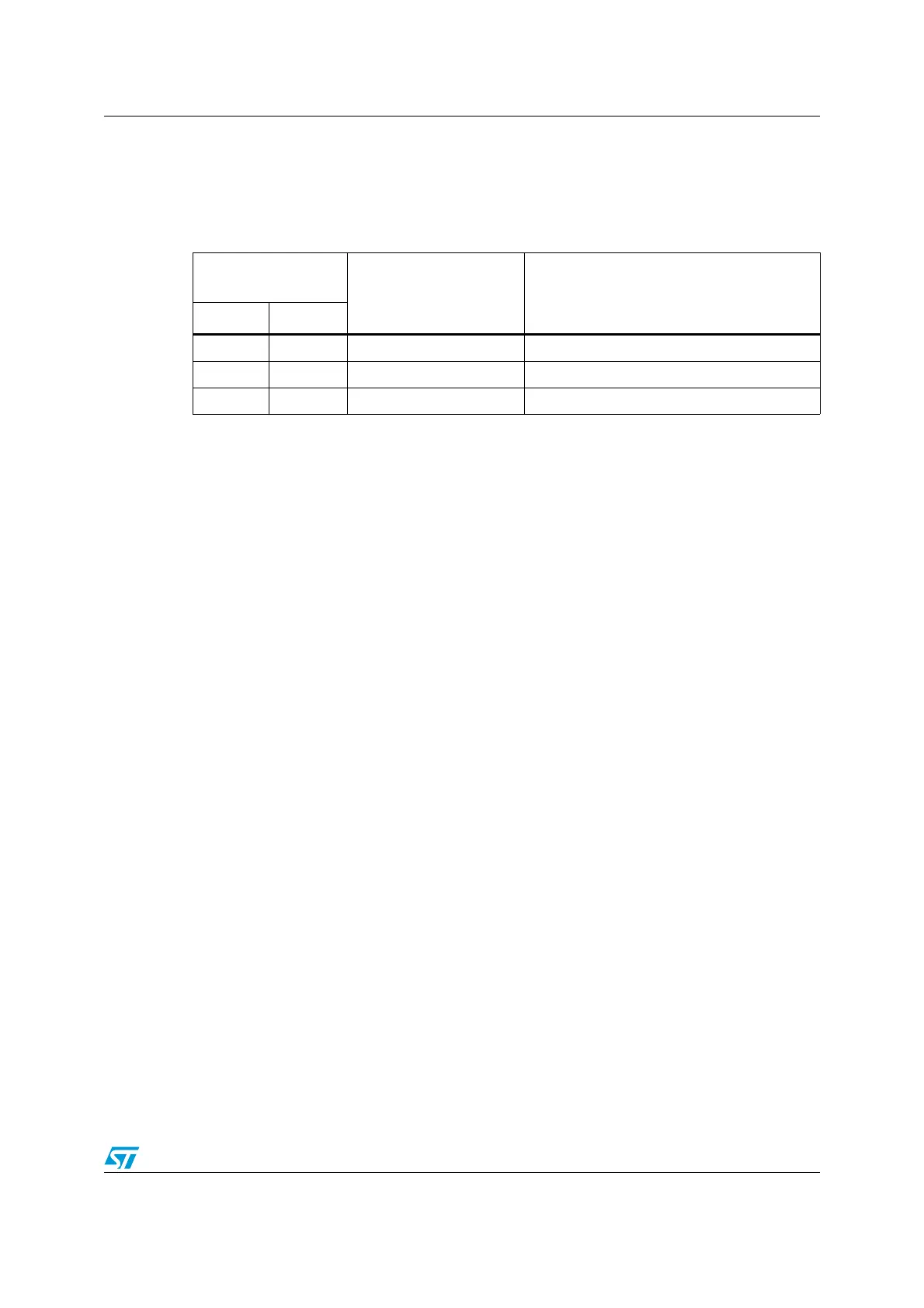
Table 5. Boot modes
Boot mode
selection pins
Boot mode Aliasing
BOOT1 BOOT0
x 0 Main Flash memory Main Flash memory is selected as boot space
0 1 System memory System memory is selected as boot space
1 1 Embedded SRAM Embedded SRAM is selected as boot space
 Loading...


