Universal synchronous asynchronous receiver transmitter (USART) RM0008
624/690
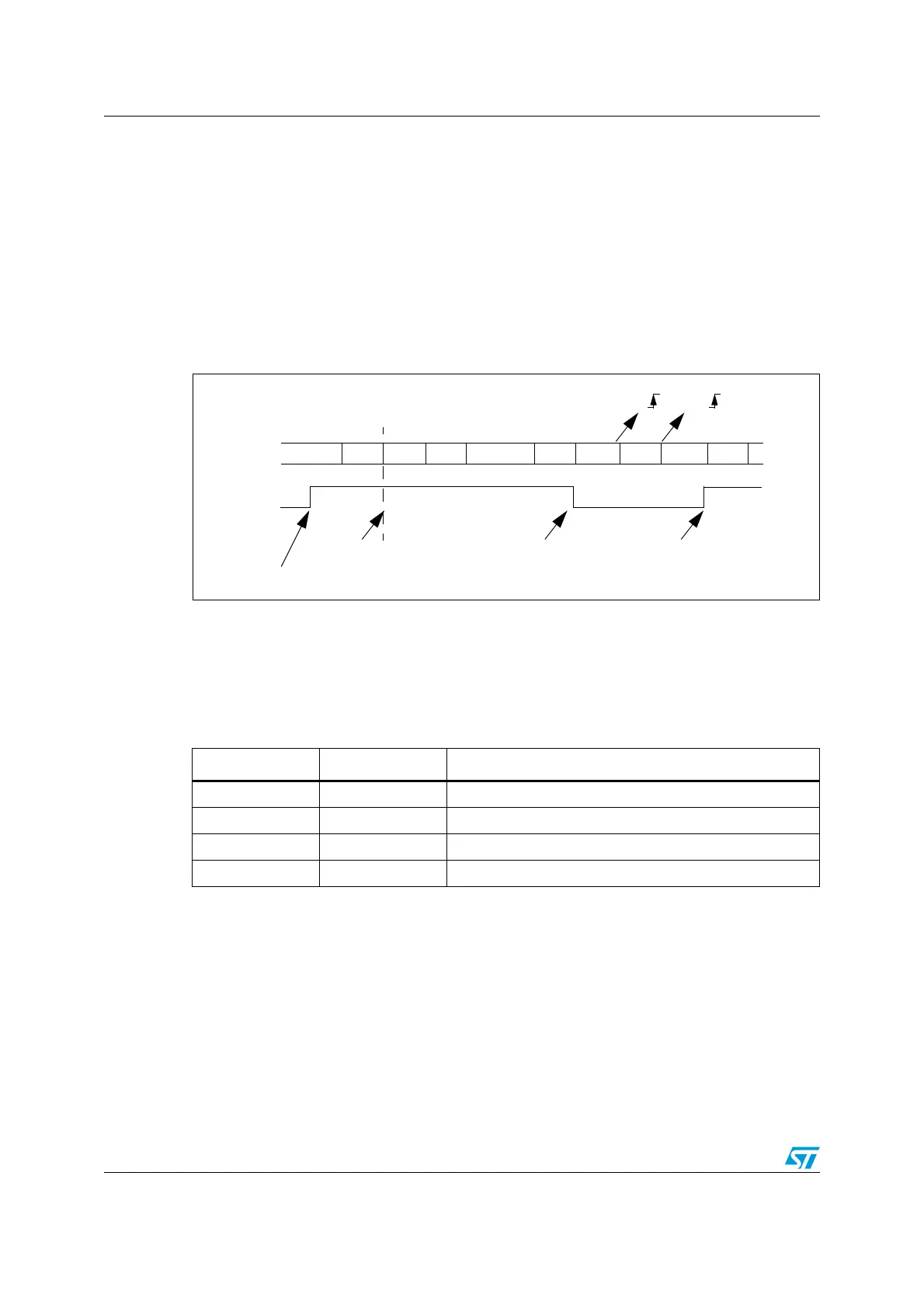
The USART enters mute mode when an address character is received which does not
match its programmed address. The RXNE flag is not set for this address byte and no
interrupt nor DMA request is issued as the USART would have entered mute mode.
It exits from mute mode when an address character is received which matches the
programmed address. Then the RWU bit is cleared and subsequent bytes are received
normally. The RXNE bit is set for the address character since the RWU bit has been cleared.
The RWU bit can be written to as 0 or 1 when the receiver buffer contains no data (RXNE=0
in the USART_SR register). Otherwise the write attempt is ignored.
An example of mute mode behavior using address mark detection is given in Figure 243.
Figure 243. Mute mode using Address mark detection
24.3.6 Parity control
Parity control (generation of parity bit in transmission and parity checking in reception) can
be enabled by setting the PCE bit in the USART_CR1 register. Depending on the frame
length defined by the M bit, the possible USART frame formats are as listed in Tabl e 1 5 4.
Table 154. Frame formats
Legends: SB: Start Bit, STB: Stop Bit, PB: Parity Bit
Note: In case of wake up by an address mark, the MSB bit of the data is taken into account and
not the parity bit
Even parity: the parity bit is calculated to obtain an even number of “1s” inside the frame
made of the 7 or 8 LSB bits (depending on whether M is equal to 0 or 1) and the parity bit.
Ex: data=00110101; 4 bits set => parity bit will be 0 if even parity is selected (PS bit in
USART_CR1 = 0).
Odd parity: the parity bit is calculated to obtain an odd number of “1s” inside the frame
made of the 7 or 8 LSB bits (depending on whether M is equal to 0 or 1) and the parity bit.
RWU written to 1
IDLE
RX
Addr=0
RWU
Mute Mode Normal Mode
Matching address
RXNE RXNE
(RXNE was cleared)
Data 2 Data 3 Data 4 Data 5Data 1 IDLE Addr=1 Addr=2
Mute Mode
In this example, the current address of the receiver is 1
(programmed in the USART_CR2 register)
Non-matching address
Non-matching address
M bit PCE bit USART frame
0 0 | SB | 8 bit data | STB |
0 1 | SB | 7-bit data | PB | STB |
1 0 | SB | 9-bit data | STB |
1 1 | SB | 8-bit data PB | STB |
 Loading...


