Inter-integrated circuit (I
2
C) interface RM0008
596/690
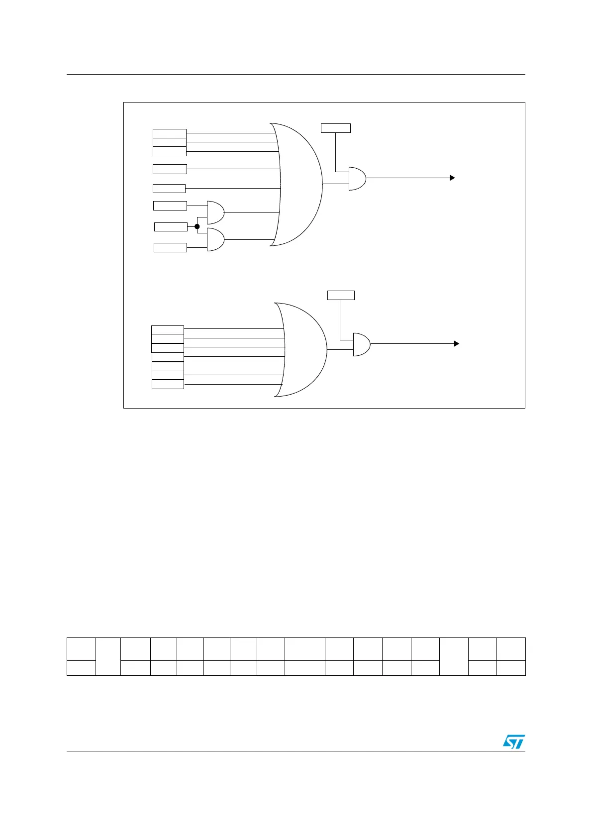
Figure 236. I
2
C interrupt mapping diagram
23.5 I
2
C debug mode
When the microcontroller enters the debug mode (Cortex-M3 core halted), the SMBUS
timeout either continues to work normally or stops, depending on the
DBG_I2Cx_SMBUS_TIMEOUT configuration bits in the DBG module. For more details,
refer to Section 26.15.2: Debug support for timers, watchdog, bxCAN and I2C on page 670.
23.6 I
2
C registers
Refer to Section 1.1 on page 32 for a list of abbreviations used in register descriptions.
23.6.1 Control register 1(I2C_CR1)
Address offset: 0x00
Reset value: 0x0000
ADDR
SB
ADD10
RxNE
TxE
BTF
it_event
ARLO
BERR
AF
OVR
PECERR
TIMEOUT
SMBAlert
ITERREN
it_error
ITEVFEN
ITBUFEN
STOPF
15141312111098 7 6543210
SW
RST
Res.
ALERT PEC POS ACK STOP START
NO
STRETCH
ENGC
EN
PEC
EN
ARP
SMB
TYPE
Res.
SM
BUS
PE
rw rw rw rw rw rw rw rw rw rw rw rw rw rw