Power control (PWR) RM0008
48/690
4 Power control (PWR)
Low-density devices are STM32F101xx, STM32F102xx and STM32F103xx
microcontrollers where the Flash memory density ranges between 16 and 32 Kbytes.
Medium-density devices are STM32F101xx, STM32F102xx and STM32F103xx
microcontrollers where the Flash memory density ranges between 64 and 128 Kbytes.
High-density devices are STM32F101xx and STM32F103xx microcontrollers where the
Flash memory density ranges between 256 and 512 Kbytes.
This section applies to the whole STM32F10xxx family, unless otherwise specified.
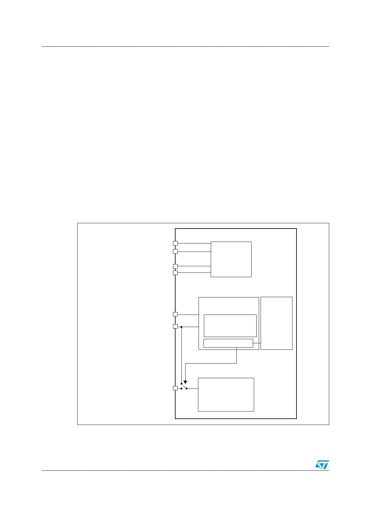
4.1 Power supplies
The device requires a 2.0-to-3.6 V operating voltage supply (V
DD
). An embedded regulator
is used to supply the internal 1.8 V digital power.
The real-time clock (RTC) and backup registers can be powered from the V
BAT
voltage when
the main V
DD
supply is powered off.
Figure 4. Power supply overview
Note: 1 V
DDA
and V
SSA
must be connected to V
DD
and V
SS
, respectively.
A/D converter
V
DDA
V
DD
V
SSA
V
REF+
V
BAT
V
SS
I/O Ring
(V
DD
)
(from 2.4 V up to V
DDA
)
BKP registers
Temp. sensor
Reset block
Standby circuitry
PLL
(Wakeup logic,
IWDG)
RTC
Voltage Regulator
Core
Memories
digital
peripherals
Low voltage detector
V
REF-
V
DDA
domain
V
DD
domain
1.8 V domain
Backup domain
LSE crystal 32K osc
RCC BDCR register
(V
SSA
)
(V
SS
)
 Loading...


