RM0008 USB full speed device interface (USB)
497/690
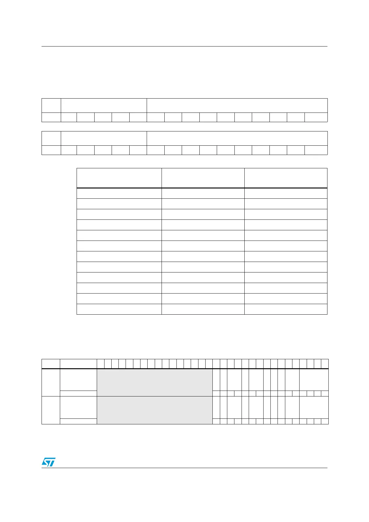
Note: Double-buffered and Isochronous IN Endpoints have two USB_COUNTn_TX
registers: named USB_COUNTn_TX_1 and USB_COUNTn_TX_0 with the
following content.
20.5.4 USB register map
The table below provides the USB register map and reset values.
31 30 29 28 27 26 25 24 23 22 21 20 19 18 17 16
BLSIZE
_1
NUM_BLOCK_1[4:0] COUNTn_RX_1[9:0]
rwrwrwrwrwrwrrrrrrrrr r
151413121110987654321 0
BLSIZE
_0
NUM_BLOCK_0[4:0] COUNTn_RX_0[9:0]
rwrwrwrwrwrwrrrrrrrrr r
Table 141. Definition of allocated buffer memory
Value of
NUM_BLOCK[4:0]
Memory allocated
when BL_SIZE=0
Memory allocated
when BL_SIZE=1
0 (‘00000’) Not allowed 32 bytes
1 (‘00001’) 2 bytes 64 bytes
2 (‘00010’) 4 bytes 96 bytes
3 (‘00011’) 6 bytes 128 bytes
... ... ...
15 (‘01111’) 30 bytes 512 bytes
16 (‘10000’) 32 bytes N/A
17 (‘10001’) 34 bytes N/A
18 (‘10010’) 36 bytes N/A
... ... ...
30 (‘11110’) 60 bytes N/A
31 (‘11111’) 62 bytes N/A
Table 142. USB register map and reset values
Offset Register
31
30
29
28
27
26
25
24
23
22
21
20
19
18
17
16
15
14
13
12
11
10
9
8
7
6
5
4
3
2
1
0
0x00
USB_EP0R
Reserved
CTR_RX
DTOG_RX
STAT_
RX
[1:0]
SETUP
EP
TYPE
[1:0]
EP_KIND
CTR_TX
DTOG_TX
STAT_
TX
[1:0]
EA[3:0]
Reset value 0000000000000000
0x04
USB_EP1R
Reserved
CTR_RX
DTOG_RX
STAT_
RX
[1:0]
SETUP
EP
TYPE
[1:0]
EP_KIND
CTR_TX
DTOG_TX
STAT_
TX
[1:0]
EA[3:0]
Reset value 0000000000000000
 Loading...


