Universal synchronous asynchronous receiver transmitter (USART) RM0008
638/690
24.5 USART mode configuration
24.6 USART registers
Refer to Section 1.1 on page 32 for a list of abbreviations used in register descriptions.
24.6.1 Status register (USART_SR)
Address offset: 0x00
Reset value: 0x00C0
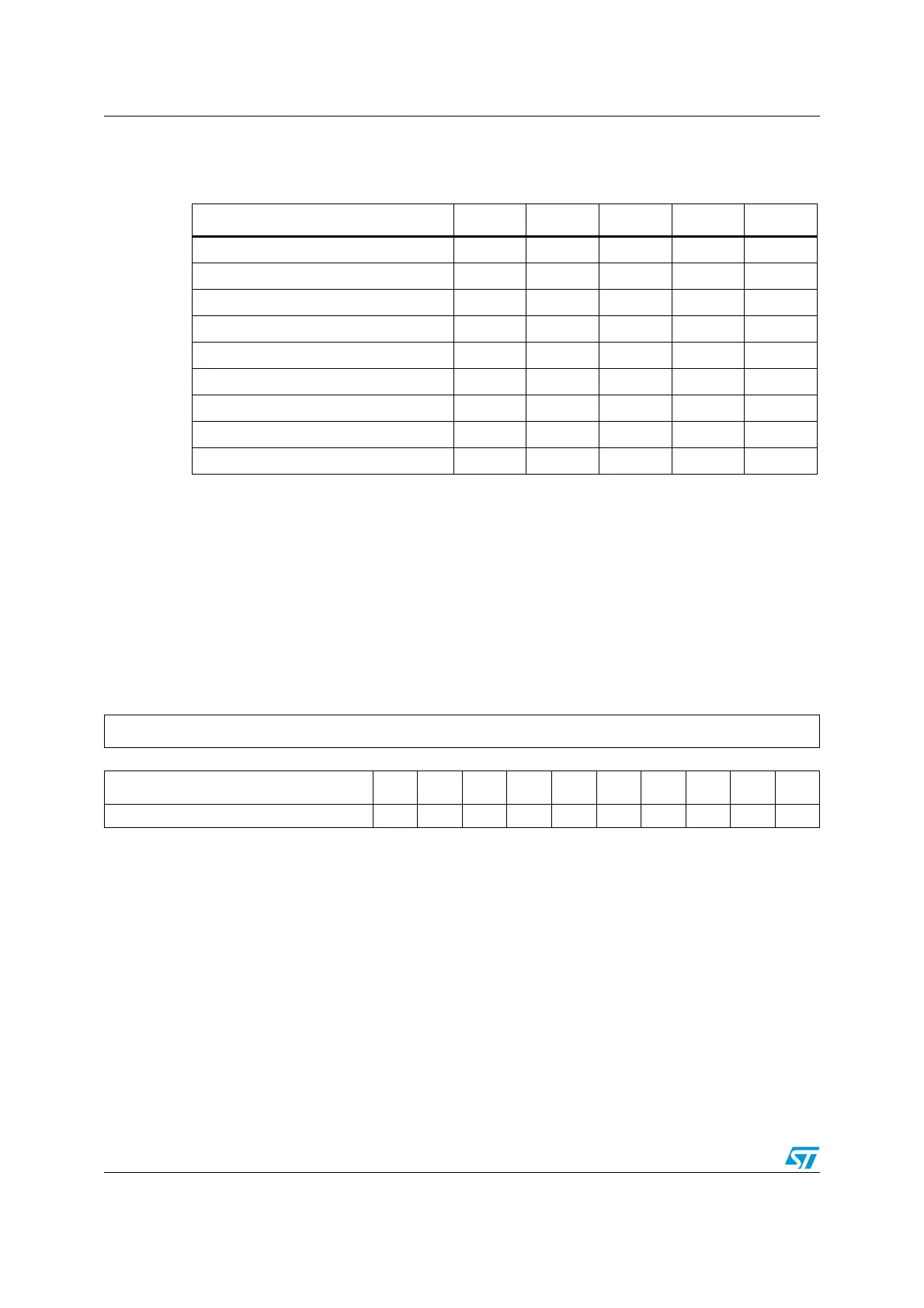
Table 156. USART modes configuration
(1)
1. X = supported; NA = not applicable.
USART modes USART1 USART2 USART3 UART4 UART5
Asynchronous mode X X X X X
Hardware Flow Control X X X NA NA
Multibuffer Communication (DMA) X X X X NA
Multiprocessor Communication X X X X X
Synchronous X X X NA NA
Smartcard XXXNANA
Half-Duplex (Single-Wire mode) X X X X X
IrDA XXXXX
LIN XXXXX
31 30 29 28 27 26 25 24 23 22 21 20 19 18 17 16
Reserved
1514131211109876543210
Reserved CTS LBD TXE TC RXNE IDLE ORE NE FE PE
Res. rc_w0rc_w0rrc_w0rc_w0rrrrr
Bits 31:10 Reserved, forced by hardware to 0.
Bit 9 CTS: CTS Flag
This bit is set by hardware when the nCTS input toggles, if the CTSE bit is set. It is cleared by
software (by writing it to 0). An interrupt is generated if CTSIE=1 in the USART_CR3 register.
0: No change occurred on the nCTS status line
1: A change occurred on the nCTS status line
Note: This bit is not available for UART4 & UART5.
Bit 8 LBD: LIN Break Detection Flag
This bit is set by hardware when the LIN break is detected. It is cleared by software (by writing it to
0). An interrupt is generated if LBDIE = 1 in the USART_CR2 register.
0: LIN Break not detected
1: LIN break detected
Note: An interrupt is generated when LBD=1 if LBDIE=1
 Loading...


