Universal synchronous asynchronous receiver transmitter (USART) RM0008
618/690
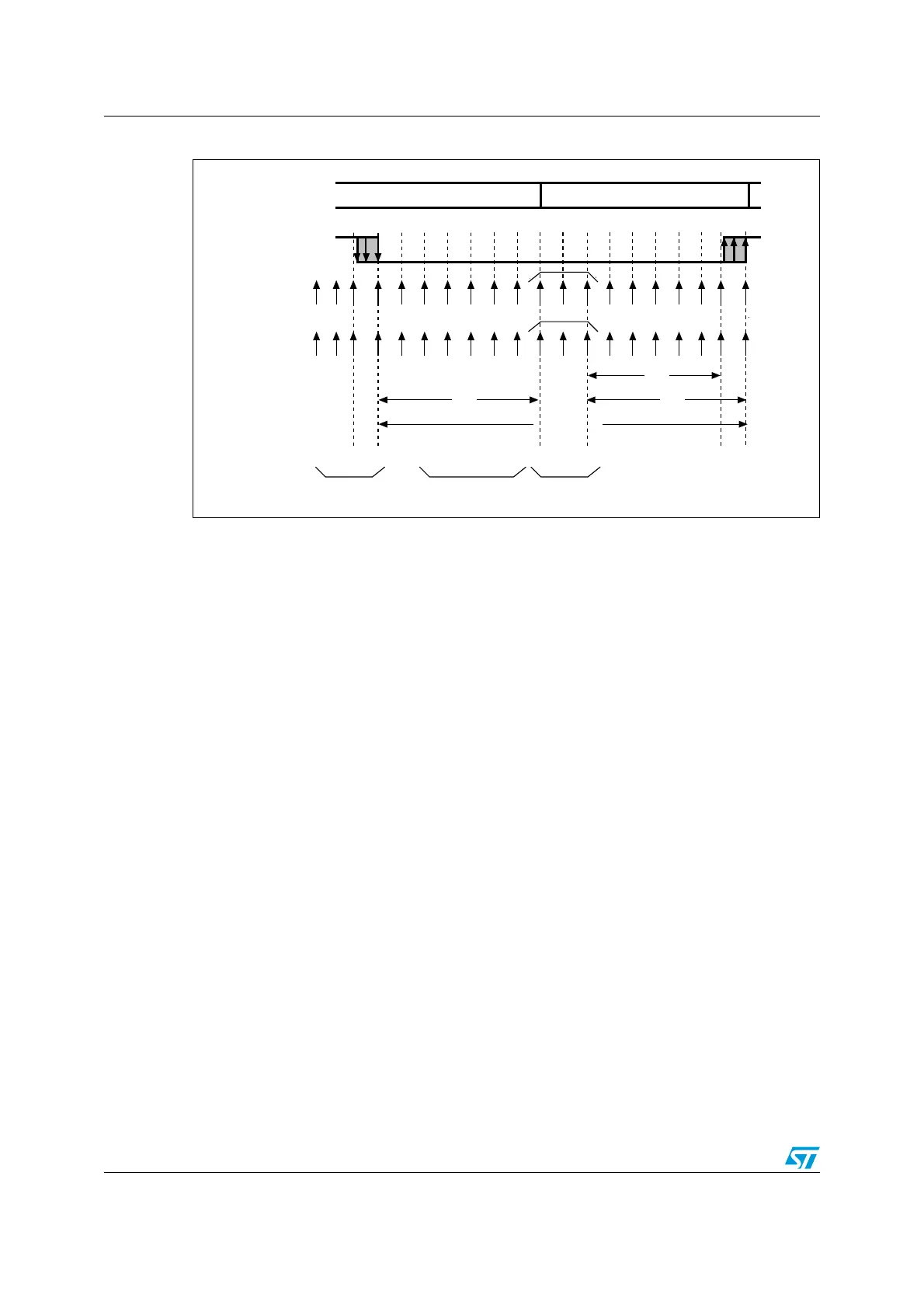
Figure 240. Start bit detection
Note: If the sequence is not complete, the start bit detection aborts and the receiver returns to idle
state (no flag is set) waiting for a falling edge.
If only 2 out of the 3 bits are at 0 (sampling on the 3
rd
, 5
th
and 7
th
bits or sampling on the 8
th
,
9
th
and 10
th
bits), the start bit is validated but the NE noise flag bit is set.
The start bit is confirmed if the last 3 samples are at 0 (sampling on the 8
th
, 9
th
, and 10
th
bits.
Character reception
During an USART reception, data shifts in least significant bit first through the RX pin. In this
mode, the USART_DR register consists of a buffer (RDR) between the internal bus and the
received shift register.
Procedure:
1. Enable the USART by writing the UE bit in USART_CR1 register to 1.
2. Program the M bit in USART_CR1 to define the word length.
3. Program the number of stop bits in USART_CR2.
4. Select DMA enable (DMAR) in USART_CR3 if multibuffer communication is to take
place. Configure the DMA register as explained in multibuffer communication. STEP 3
5. Select the desired baud rate using the baud rate register USART_BRR
6. Set the RE bit USART_CR1. This enables the receiver which begins searching for a
start bit.
RX line
sampled values
Idle Start bitRX state
Real
sample
clock
Ideal
sample
clock
010X0X0000XXXXXX
Conditions
to validate
the start bit
At least 2 bits
out of 3 at 0
At least 2 bits
out of 3 at 0
Falling edge
detection
11
1 2 3 4 5 6 7 8 9 10 11 12 13 14 15 16
X X X X X X X X 9 10 111213141516
6/16
7/16
One-bit time
7/16
X
ai15471
 Loading...


