RM0008 DMA controller (DMA)
135/690
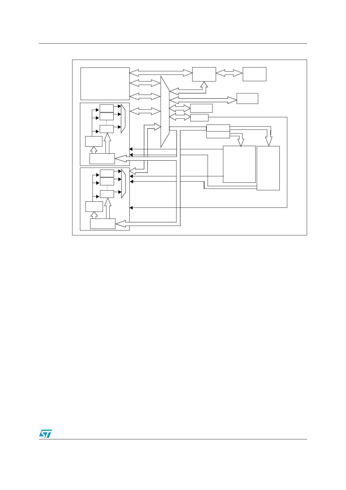
Figure 18. DMA block diagram
1. The DMA2 controller is available only in high-density devices.
2. ADC3, SPI/I2S3, UART4, SDIO, TIM5, TIM6, DAC, TIM7, TIM8 DMA requests are available only in high-
density devices.
9.3 DMA functional description
The DMA controller performs direct memory transfer by sharing the system bus with the
Cortex™-M3 core. The DMA request may stop the CPU access to the system bus for some
bus cycles, when the CPU and DMA are targeting the same destination (memory or
peripheral). The bus matrix implements round-robin scheduling, thus ensuring at least half
of the system bus bandwidth (both to memory and peripheral) for the CPU.
9.3.1 DMA transactions
After an event, the peripheral sends a request signal to the DMA Controller. The DMA
controller serves the request depending on the channel priorities. As soon as the DMA
Controller accesses the peripheral, an Acknowledge is sent to the peripheral by the DMA
Controller. The peripheral releases its request as soon as it gets the Acknowledge from the
DMA Controller. Once the request is deasserted by the peripheral, the DMA Controller
release the Acknowledge. If there are more requests, the peripheral can initiate the next
transaction.
FLITF
Ch.1
Ch.2
Ch.7
Arbiter
Cortex-M3
SRAM
AHB Slave
DMA1
ICode
DCode
System
AHB System
DMA request
APB2
Flash
Bridge 2
Bridge 1
USART1
SPI1
ADC1
ADC3
USART2
USART3
UART4
I2C2
I2C1
TIM2
TIM3
TIM 4
Ch.1
Ch.2
Ch.5
Arbiter
AHB Slave
DMA2
FSMC
SDIO
APB1
DMA request
TIM1
SPI/I2S3
SPI/I2S2
TIM8
TIM5
TIM6
TIM7
ai14801
DMA request
 Loading...


