USB full speed device interface (USB) RM0008
494/690
20.5.3 Buffer descriptor table
Although the buffer descriptor table is located inside the packet buffer memory, its entries
can be considered as additional registers used to configure the location and size of the
packet buffers used to exchange data between the USB macro cell and the STM32F10xxx.
Due to the common APB bridge limitation on word addressability, all packet memory
locations are accessed by the APB using 32-bit aligned addresses, instead of the actual
memory location addresses utilized by the USB peripheral for the USB_BTABLE register
and buffer description table locations.
In the following pages two location addresses are reported: the one to be used by
application software while accessing the packet memory, and the local one relative to USB
Peripheral access. To obtain the correct STM32F10xxx memory address value to be used in
the application software while accessing the packet memory, the actual memory location
address must be multiplied by two. The first packet memory location is located at
0x4000 6000. The buffer descriptor table entry associated with the USB_EPnR registers is
described below.
A thorough explanation of packet buffers and the buffer descriptor table usage can be found
in Structure and usage of packet buffers on page 472.
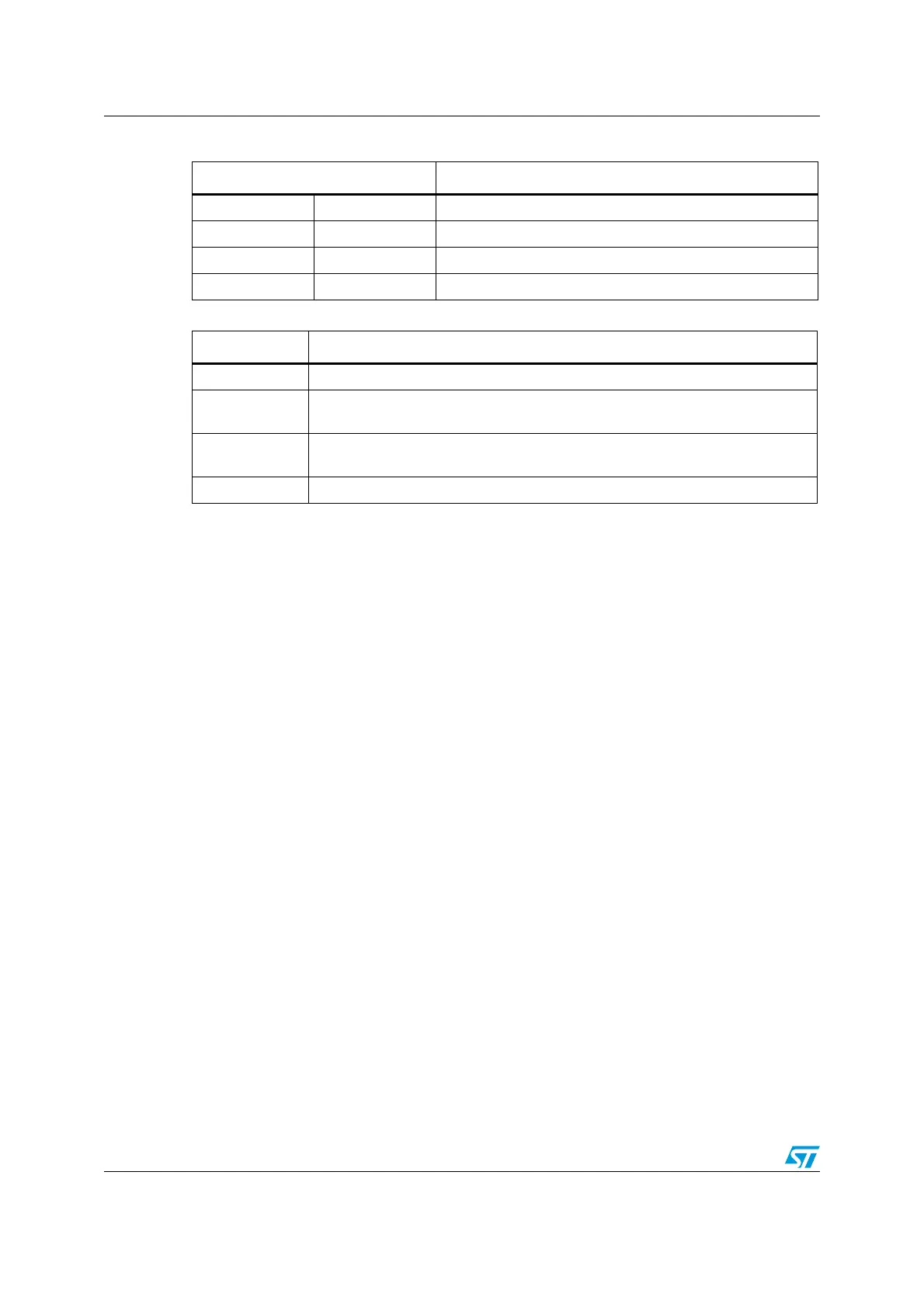
Table 139. Endpoint kind meaning
EP_TYPE[1:0] EP_KIND Meaning
00 BULK DBL_BUF
01 CONTROL STATUS_OUT
10 ISO Not used
11 INTERRUPT Not used
Table 140. Transmission status encoding
STAT_TX[1:0] Meaning
00 DISABLED: all transmission requests addressed to this endpoint are ignored.
01
STALL: the endpoint is stalled and all transmission requests result in a STALL
handshake.
10
NAK: the endpoint is naked and all transmission requests result in a NAK
handshake.
11 VALID: this endpoint is enabled for transmission.
 Loading...


