RM0008 General-purpose and alternate-function I/Os (GPIOs and AFIOs)
99/690
7.1.1 General-purpose I/O (GPIO)
During and just after reset, the alternate functions are not active and the I/O ports are
configured in Input Floating mode (CNFx[1:0]=01b, MODEx[1:0]=00b).
The JTAG pins are in input PU/PD after reset:
PA15: JTDI in PU
PA14: JTCK in PD
PA13: JTMS in PU
PB4: JNTRST in PU
When configured as output, the value written to the Output Data register (GPIOx_ODR) is
output on the I/O pin. It is possible to use the output driver in Push-Pull mode or Open-Drain
mode (only the N-MOS is activated when outputting 0).
The Input Data register (GPIOx_IDR) captures the data present on the I/O pin at every
APB2 clock cycle.
All GPIO pins have a internal weak pull-up and weak pull-down which can be activated or
not when configured as input.
7.1.2 Atomic bit set or reset
There is no need for the software to disable interrupts when programming the GPIOx_ODR
at bit level: it is possible to modify only one or several bits in a single atomic APB2 write
access. This is achieved by programming to ‘1’ the Bit Set/Reset Register (GPIOx_BSRR,
or for reset only GPIOx_BRR) to select the bits you want to modify. The unselected bits will
not be modified.
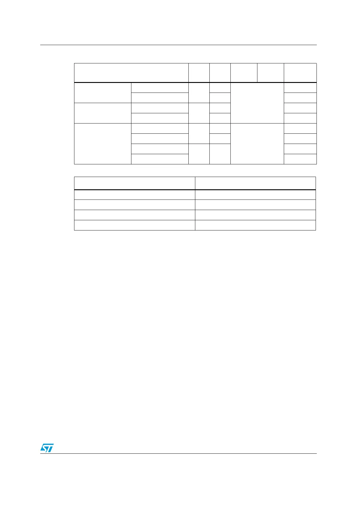
Table 15. Port bit configuration table
Configuration mode CNF1 CNF0 MODE1 MODE0
PxODR
Register
General purpose
output
Push-pull
0
0
01
10
11
see Ta bl e 1 6
0 or 1
Open-drain 1 0 or 1
Alternate Function
output
Push-pull
1
0 don’t care
Open-drain 1 don’t care
Input
Analog input
0
0
00
don’t care
Input floating 1 don’t care
Input pull-down
10
0
Input pull-up 1
Table 16. Output MODE bits
MODE[1:0] Meaning
00 Reserved
01 Max. output speed 10 MHz
10 Max. output speed 2 MHz
11 Max. output speed 50 MHz
 Loading...


