USB full speed device interface (USB) RM0008
474/690
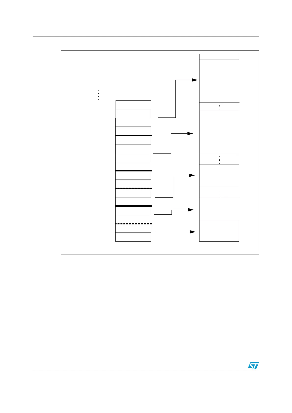
Figure 190. Packet buffer areas with examples of buffer description table locations
Each packet buffer is used either during reception or transmission starting from the bottom.
The USB peripheral will never change the contents of memory locations adjacent to the
allocated memory buffers; if a packet bigger than the allocated buffer length is received
(buffer overrun condition) the data will be copied to the memory only up to the last available
location.
Endpoint initialization
The first step to initialize an endpoint is to write appropriate values to the
ADDRn_TX/ADDRn_RX registers so that the USB peripheral finds the data to be
transmitted already available and the data to be received can be buffered. The EP_TYPE
bits in the USB_EPnR register must be set according to the endpoint type, eventually using
the EP_KIND bit to enable any special required feature. On the transmit side, the endpoint
must be enabled using the STAT_TX bits in the USB_EPnR register and COUNTn_TX must
be initialized. For reception, STAT_RX bits must be set to enable reception and
COUNTn_RX must be written with the allocated buffer size using the BL_SIZE and
Buffer for
double-buffered
IN Endpoint 3
ADDR0_TX
COUNT0_TX
0000_0000 (00)
ADDR0_RX
COUNT0_RX
ADDR1_TX
COUNT1_TX
ADDR1_RX
COUNT1_RX
ADDR2_RX_0
COUNT2_RX_0
ADDR2_RX_1
COUNT2_RX_1
ADDR3_TX_0
COUNT3_TX_0
0000_0010 (02)
0000_0100 (04)
0000_0110 (06)
0000_1000 (08)
0000_1010 (0A)
0000_1100 (0C)
0000_1110 (0E)
0001_0000 (10)
0001_0010 (12)
0001_0100 (14)
0001_0110 (16)
0001_1000 (18)
0001_1010 (1A)
Buffer description table locations
Transmission
buffer for
Endpoint 0
Reception buffer
for
Endpoint 0
Transmission
buffer for
single-buffered
Endpoint 1
Packet buffers
ADDR3_TX_1
COUNT3_TX_1
0001_1100 (1C)
0001_1110 (1E)
Buffer for
double-buffered
OUT Endpoint 2
 Loading...


