Flexible static memory controller (FSMC) RM0008
366/690
● Write FIFO, 16 words long, each word 32 bits wide. This makes it possible to write to
slow memories and free the AHB quickly for other transactions. If a new transaction is
started to the FSMC, first the FIFO is drained
The FSMC registers that define the external device type and associated characteristics are
usually set at boot time and do not change until the next reset or power-up. However, it is
possible to change the settings at any time.
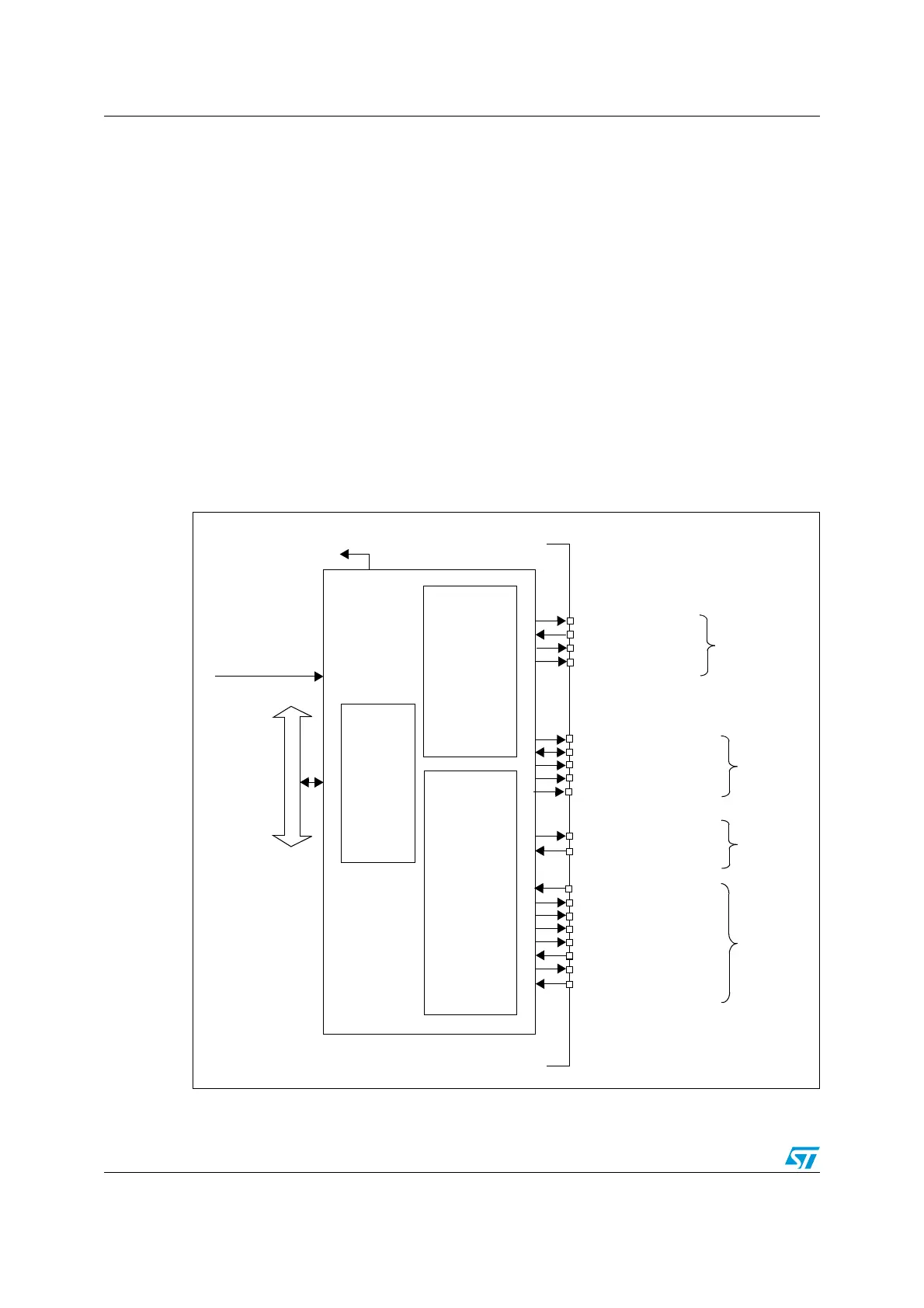
18.2 Block diagram
The FSMC consists of four main blocks:
● The AHB interface (including the FSMC configuration registers)
● The NOR Flash/PSRAM controller
● The NAND Flash/PC Card controller
● The external device interface
The block diagram is shown in Figure 157.
Figure 157. FSMC block diagram
AHB bus
FSMC interrupt to NVIC
NOR
HCLK
From clock
controller
controller
memory
NAND/PC Card
controller
memory
Configuration
Registers
signals
NAND
signals
Shared
signals
NOR/PSRAM
FSMC_NE[4:1]
FSMC_NL (or NADV)
FSMC_NWAIT
FSMC_A[25:0]
FSMC_D[15:0]
FSMC_NOE
FSMC_NWE
FSMC_NIORD
FSMC_NREG
FSMC_CD
signals
PC Card
ai14718b
FSMC_NBL[1:0]
FSMC_NCE[3:2]
FSMC_INT[3:2]
FSMC_INTR
FSMC_NCE4_1
FSMC_NCE4_2
FSMC_NIOWR
FSMC_NIOS16
FSMC_CLK
 Loading...


