DocID024597 Rev 5 1353/1830
RM0351 Universal synchronous asynchronous receiver transmitter (USART)
1411
Note: The 3 bits (CPOL, CPHA, LBCL) should not be written while the transmitter is enabled.
40.8.3 Control register 3 (USART_CR3)
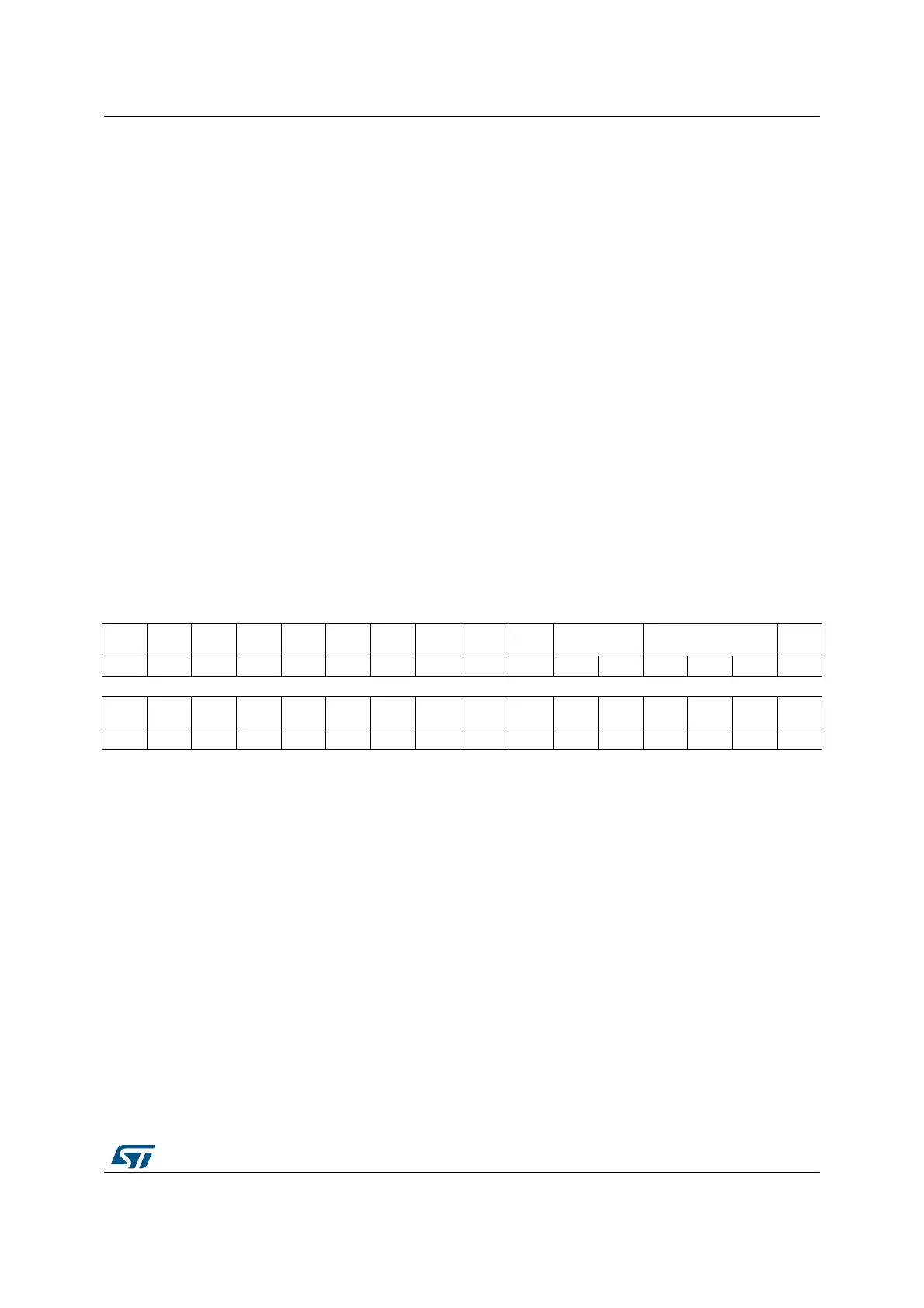
Address offset: 0x08
Reset value: 0x0000
Bit 5 LBDL: LIN break detection length
This bit is for selection between 11 bit or 10 bit break detection.
0: 10-bit break detection
1: 11-bit break detection
This bit can only be written when the USART is disabled (UE=0).
Note: If LIN mode is not supported, this bit is reserved and forced by hardware to ‘0’. Please refer to
Section 40.4: USART implementation on page 1304.
Bit 4 ADDM7:7-bit Address Detection/4-bit Address Detection
This bit is for selection between 4-bit address detection or 7-bit address detection.
0: 4-bit address detection
1: 7-bit address detection (in 8-bit data mode)
This bit can only be written when the USART is disabled (UE=0)
Note: In 7-bit and 9-bit data modes, the address detection is done on 6-bit and 8-bit address
(ADD[5:0] and ADD[7:0]) respectively.
Bits 3:0 Reserved, must be kept at reset value.
31 30 29 28 27 26 25 24 23 22 21 20 19 18 17 16
Res. Res. Res. Res. Res. Res. Res.
TCBGT
IE
UCESM WUFIE WUS SCARCNT2:0] Res.
rw rw rw rw rw rw rw rw
15141312111098 7 6543210
DEP DEM DDRE
OVR
DIS
ONE
BIT
CTSIE CTSE RTSE DMAT DMAR SCEN NACK HDSEL IRLP IREN EIE
rw rw rw rw rw rw rw rw rw rw v v rw rw rw rw
Bits 31:25 Reserved, must be kept at reset value.
Bit 24 TCBGTIE: Transmission complete before guard time interrupt enable
This bit is set and cleared by software.
0: Interrupt is inhibited
1: An USART interrupt is generated whenever TCBGT=1 in the USART_ISR register.
Note: If Smartcard mode is not supported, this bit is reserved and forced by hardware to ‘0’
(see Section 40.4: USART implementation).
Note: This bit is available on STM32L496xx/4A6xx devices only
Bit 23 UCESM: USART Clock Enable in Stop mode.
This bit is set and cleared by software.
0: USART Clock is disabled in STOP mode.
1: USART Clock is enabled in STOP mode.
 Loading...


