Clock recovery system (CRS) (only valid for STM32L496xx/4A6xx devices) RM0351
284/1830 DocID024597 Rev 5
7.6 CRS registers
Refer to Section 1.1 on page 67 of the reference manual for a list of abbreviations used in
register descriptions.
The peripheral registers can be accessed by words (32-bit).
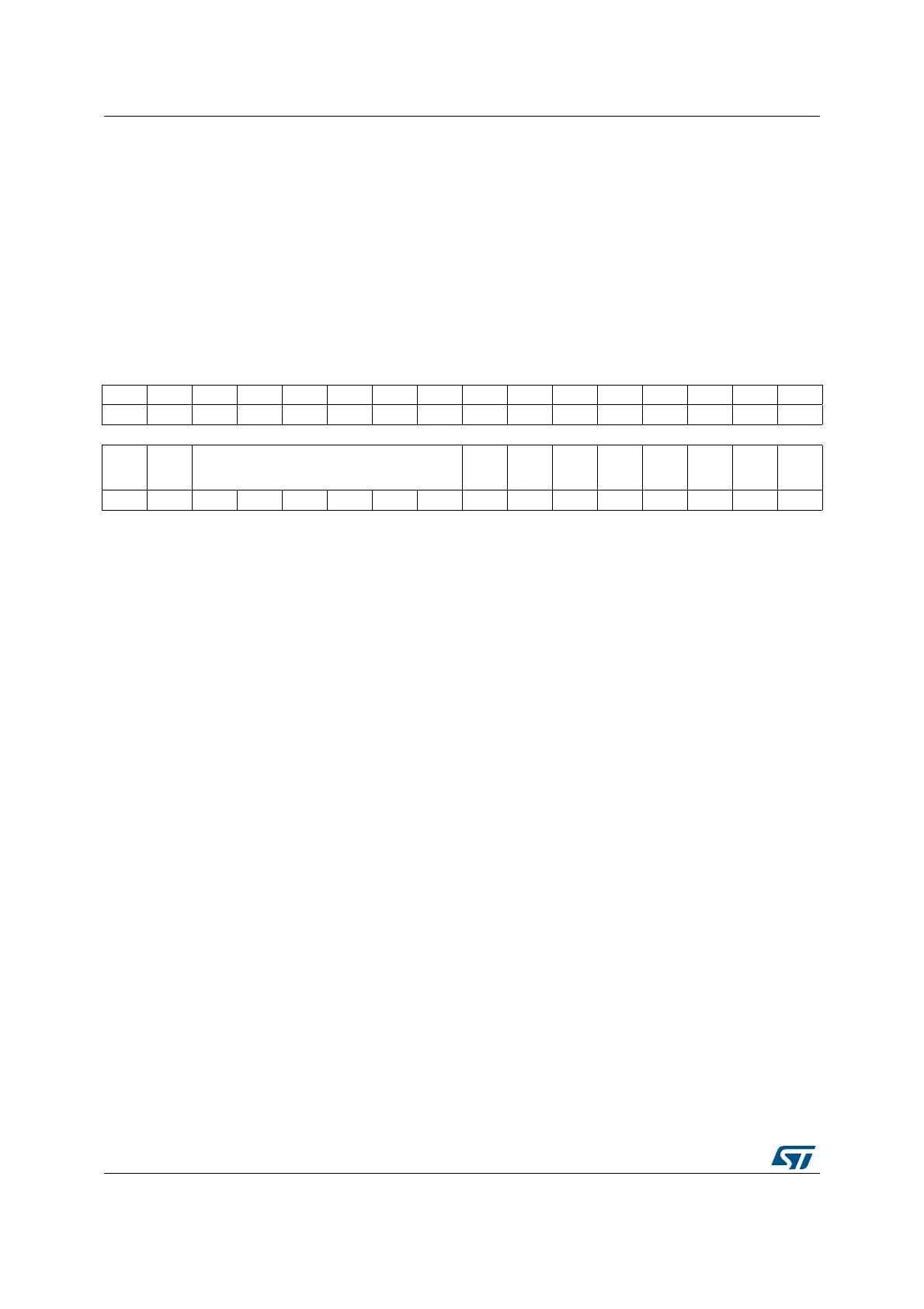
7.6.1 CRS control register (CRS_CR)
Address offset: 0x00
Reset value: 0x0000 2000
31 30 29 28 27 26 25 24 23 22 21 20 19 18 17 16
Res. Res. Res. Res. Res. Res. Res. Res. Res. Res. Res. Res. Res. Res. Res. Res.
1514131211109876543210
Res. Res. TRIM[5:0]
SWSY
NC
AUTOT
RIMEN
CEN Res.
ESYNC
IE
ERRIE
SYNC
WARNI
E
SYNCO
KIE
rw rw rw rw rw rw rt_w rw rw rw rw rw rw
Bits 31:14 Reserved, must be kept at reset value.
Bits 13:8 TRIM[5:0]: HSI48 oscillator smooth trimming
These bits provide a user-programmable trimming value to the HSI48 oscillator. They can be
programmed to adjust to variations in voltage and temperature that influence the frequency
of the HSI48.
The default value is 32, which corresponds to the middle of the trimming interval. The
trimming step is around 67 kHz between two consecutive TRIM steps. A higher TRIM value
corresponds to a higher output frequency.
When the AUTOTRIMEN bit is set, this field is controlled by hardware and is read-only.
Bit 7 SWSYNC: Generate software SYNC event
This bit is set by software in order to generate a software SYNC event. It is automatically
cleared by hardware.
0: No action
1: A software SYNC event is generated.
Bit 6 AUTOTRIMEN: Automatic trimming enable
This bit enables the automatic hardware adjustment of TRIM bits according to the measured
frequency error between two SYNC events. If this bit is set, the TRIM bits are read-only. The
TRIM value can be adjusted by hardware by one or two steps at a time, depending on the
measured frequency error value. Refer to Section 7.3.4: Frequency error evaluation and
automatic trimming for more details.
0: Automatic trimming disabled, TRIM bits can be adjusted by the user.
1: Automatic trimming enabled, TRIM bits are read-only and under hardware control.
Bit 5 CEN: Frequency error counter enable
This bit enables the oscillator clock for the frequency error counter.
0: Frequency error counter disabled
1: Frequency error counter enabled
When this bit is set, the CRS_CFGR register is write-protected and cannot be modified.
Bit 4 Reserved, must be kept at reset value.
 Loading...


