Clock recovery system (CRS) (only valid for STM32L496xx/4A6xx devices) RM0351
286/1830 DocID024597 Rev 5
7.6.3 CRS interrupt and status register (CRS_ISR)
Address offset: 0x08
Reset value: 0x0000 0000
Bits 26:24 SYNCDIV[2:0]: SYNC divider
These bits are set and cleared by software to control the division factor of the SYNC signal.
000: SYNC not divided (default)
001: SYNC divided by 2
010: SYNC divided by 4
011: SYNC divided by 8
100: SYNC divided by 16
101: SYNC divided by 32
110: SYNC divided by 64
111: SYNC divided by 128
Bits 23:16 FELIM[7:0]: Frequency error limit
FELIM contains the value to be used to evaluate the captured frequency error value latched
in the FECAP[15:0] bits of the CRS_ISR register. Refer to Section 7.3.4: Frequency error
evaluation and automatic trimming for more details about FECAP evaluation.
Bits 15:0 RELOAD[15:0]: Counter reload value
RELOAD is the value to be loaded in the frequency error counter with each SYNC event.
Refer to Section 7.3.3: Frequency error measurement for more details about counter
behavior.
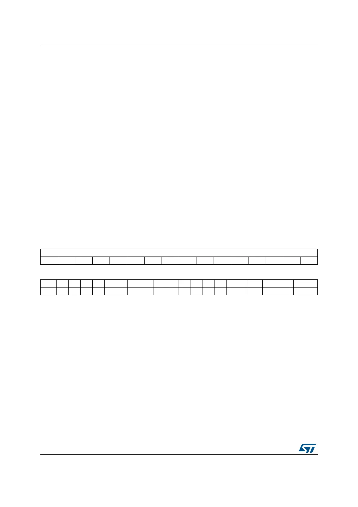
31 30 29 28 27 26 25 24 23 22 21 20 19 18 17 16
FECAP[15:0]
rrrrrrrrrrrrrrrr
1514131211 10 9 8 7654 3 2 1 0
FEDIR Res. Res. Res. Res. TRIMOVF SYNCMISS SYNCERR Res. Res. Res. Res. ESYNCF ERRF SYNCWARNF SYNCOKF
rrrr rrrr
Bits 31:16 FECAP[15:0]: Frequency error capture
FECAP is the frequency error counter value latched in the time of the last SYNC event.
Refer to Section 7.3.4: Frequency error evaluation and automatic trimming for more details
about FECAP usage.
Bit 15 FEDIR: Frequency error direction
FEDIR is the counting direction of the frequency error counter latched in the time of the last
SYNC event. It shows whether the actual frequency is below or above the target.
0: Upcounting direction, the actual frequency is above the target.
1: Downcounting direction, the actual frequency is below the target.
Bits 14:11 Reserved, must be kept at reset value.
Bit 10 TRIMOVF: Trimming overflow or underflow
This flag is set by hardware when the automatic trimming tries to over- or under-flow the
TRIM value. An interrupt is generated if the ERRIE bit is set in the CRS_CR register. It is
cleared by software by setting the ERRC bit in the CRS_ICR register.
0: No trimming error signalized
1: Trimming error signalized
 Loading...


